Electric caliper brake

a technology of caliper brake and caliper plate, which is applied in the direction of fluid actuated brake, braking system, transportation and packaging, etc., can solve the problems of increased processing cost and generated noise of manufacturing stoppers, and achieve the effect of reducing vibration and friction noise and processing cos

Active Publication Date: 2021-01-26
HL MANDO CORP
View PDF12 Cites 0 Cited by
  • Summary
  • Abstract
  • Description
  • Claims
  • Application Information

AI Technical Summary

Benefits of technology

[0008]The present invention is directed to providing an electric caliper brake capable of reducing vibration and friction noise and a processing cost for manufacturing a separate stopper.

Problems solved by technology

In the case in which the separate stopper is installed in the electric caliper brake, there are problems in that noise is generated due to vibrations and a processing cost for manufacturing stopper is increased.

Method used


Image

  • Electric caliper brake
  • Electric caliper brake
  • Electric caliper brake

Examples


Embodiment Construction

[0020]Hereinafter, embodiments of the present invention will be described in detail with reference to the accompanying drawings. The following embodiments are examples to provide the scope of the present invention to those skilled in the art. The present invention is not limited to the following embodiments and may be implemented in different forms. In the drawings, portions which are not related to the description may be omitted for clarifying the present invention, and sizes of components may be exaggerated for understanding the present invention.

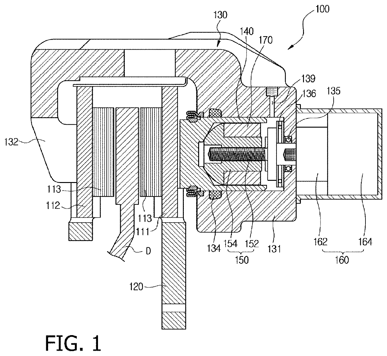
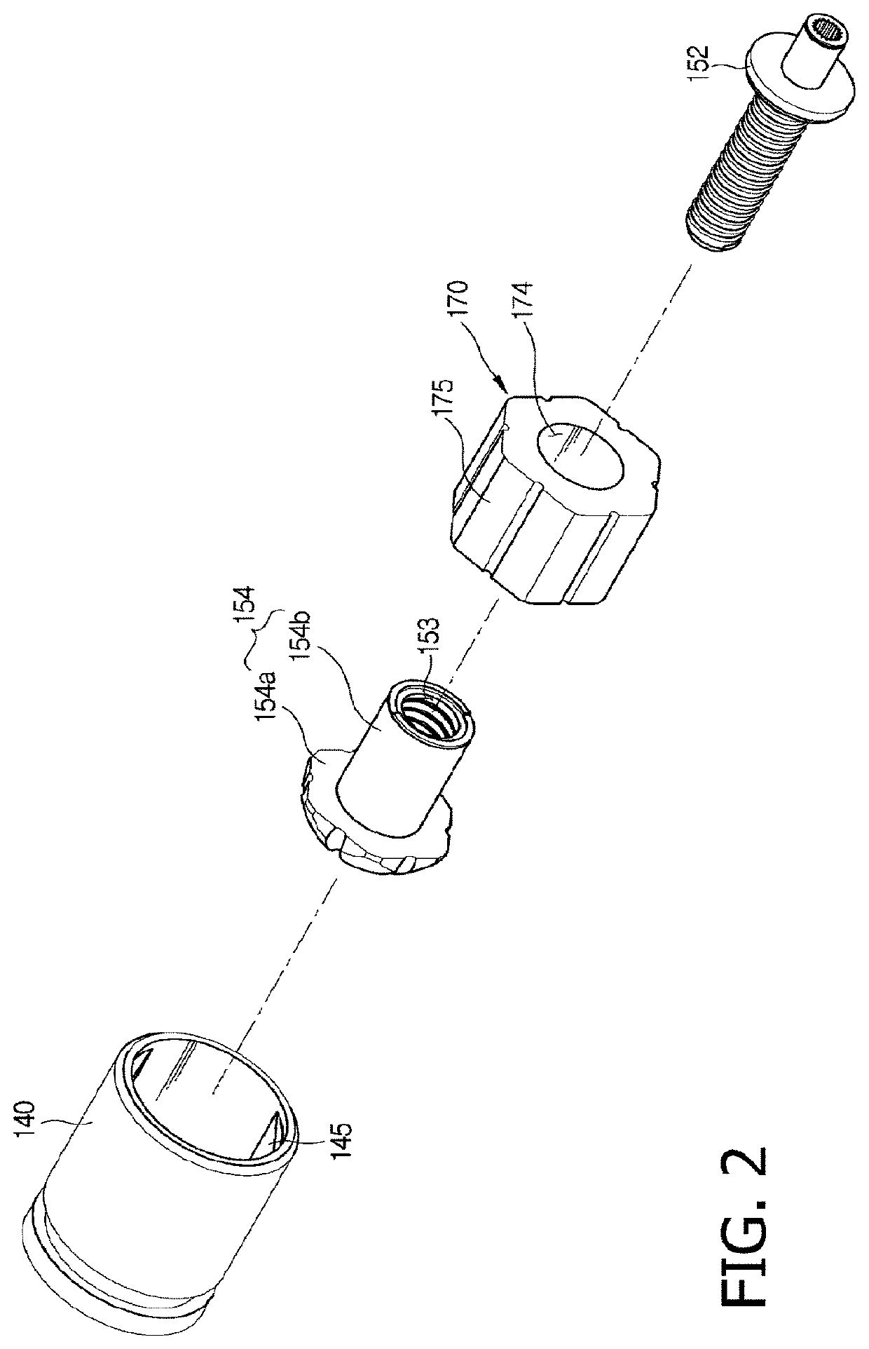
[0021]FIG. 1 is a schematic cross-sectional view illustrating an electric caliper brake according to one embodiment of the present invention. FIG. 2 is an exploded perspective view illustrating a coupling state of a piston and a power transmission module included in the electric caliper brake according to one embodiment of the present invention. Hereinafter, when the electric caliper brake according to one embodiment of the present invent...


PUM


Abstract

An electric caliper brake is provided. The electric caliper brake includes a carrier in which a pair of pad plates are installed to be movable forward and backward, and a caliper housing in which a cylinder having a piston installed to be movable forward to and backward from the carrier due to a hydraulic pressure is provided. The electric caliper brake includes a power transmission module, which includes a spindle member installed to pass through a rear portion of the cylinder and configured to receive rotational power from an actuator to rotate, and a nut member screw-coupled to the spindle member, disposed in the piston, and configured to move forward or backward according to rotation of the spindle member to operate the piston, wherein the spindle member includes a first screw thread portion corresponding to a screw thread formed on the nut member and a second screw thread portion, which is disposed to have the same axis as that of the first screw thread portion and has a pitch which is different from that of the first screw thread portion, and when the nut member rotates about the second screw thread portion, a frictional force between the screw thread of the nut member and the second screw thread increases.

Description

CROSS-REFERENCE TO RELATED APPLICATION[0001]This application claims priority to and the benefit of Korean Patent Application No. 2018-0019917, filed on Feb. 20, 2018, the disclosure of which is incorporated herein by reference in its entirety.BACKGROUND1. Field of the Invention[0002]The present invention relates to an electric caliper brake, and more specifically, to an electric caliper brake for a vehicle.2. Discussion of Related Art[0003]Generally, an electric caliper brake includes a typical hydraulic disc brake and a separate actuator which operates electrically.[0004]A conventional electric disc brake system (hereinafter, referred to as a ‘electric caliper brake’) includes a disc configured to rotate with a wheel of a vehicle, a carrier in which a pair of pad plates are installed to be movable forward and backward so as to press the disc, a caliper housing in which a cylinder, which is installed to be slidable in the carrier and in which a piston is installed to be movable forw...

Claims


Application Information

Patent Timeline
Patent Type & Authority Patents(United States)
IPC IPC(8): F16D65/18B60T13/74B60T1/06F16D55/225F16D121/24F16D125/40
CPCB60T13/741B60T1/065F16D55/225F16D65/18F16D65/183F16D2121/24F16D2125/40F16D55/32F16D65/0006F16D65/14F16D2121/04F16D2125/02F16D55/226F16D2121/14
Inventor HYEON, SE RA
Owner HL MANDO CORP
Why Eureka
Try Eureka