Fovea lens
a wide-angle lens and lens body technology, applied in the field of wide-angle lenses, can solve the problems of complex and difficult manufacturing of aspheric elements, and achieve the effect of reducing the manufacturing risk of aspheric elements and difficult manufacturing
- Summary
- Abstract
- Description
- Claims
- Application Information
AI Technical Summary
Benefits of technology
Problems solved by technology
Method used
Image
Examples
example 1
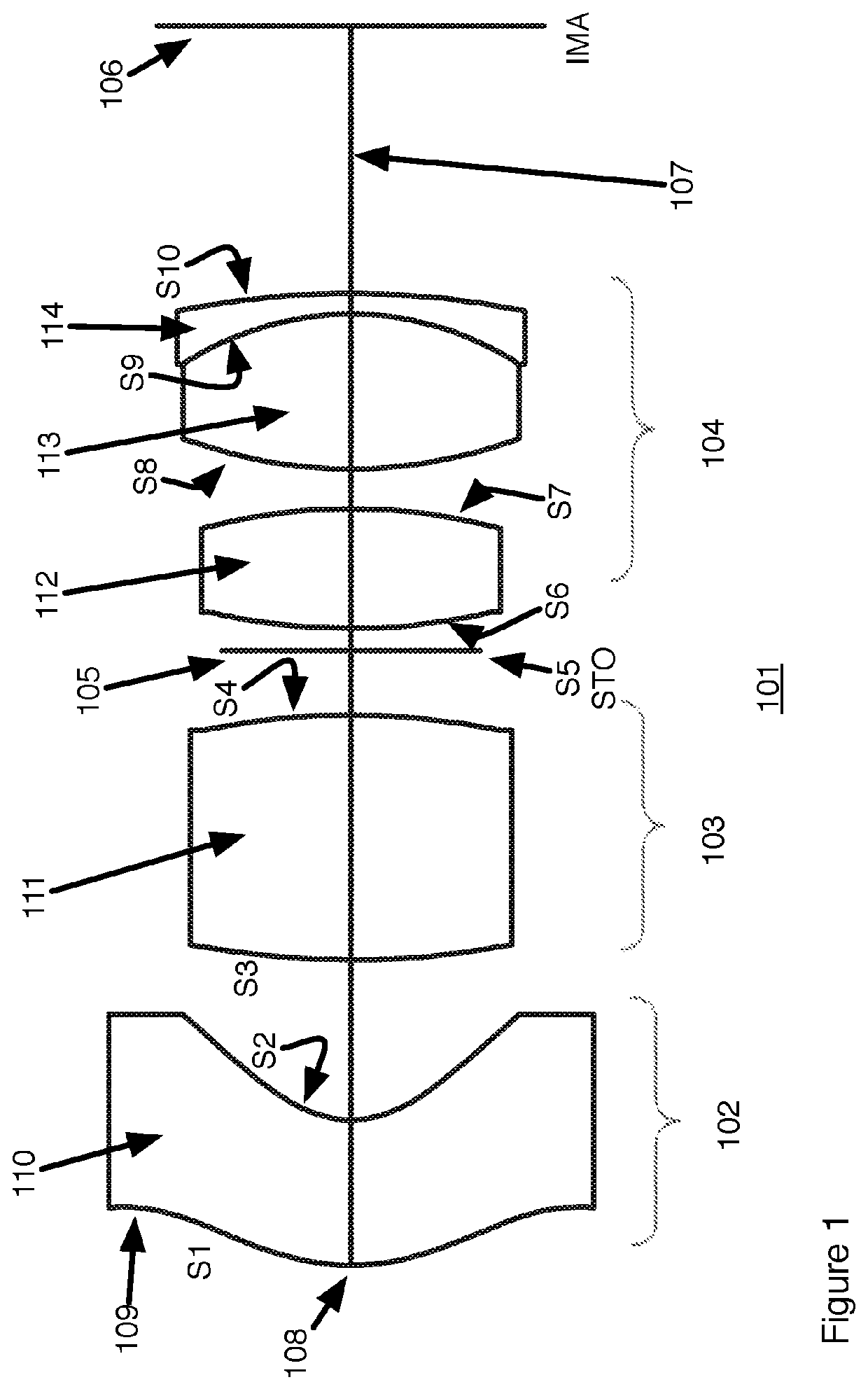
[0033]As shown and discussed in conjunction with FIG. 1, The example wide angle lens includes: Lens element number 1 (bounded by surface 1 and 2), the aspheric element, is the first lens group. Lens element number 2 (bounded by surface 3 and 4) is the second lens group. Lens element 3, 4 and 5 from surface 6 to 10 make up the 3rd group. All elements in group 2 and 3 are spherical.
[0034]
TABLE 1ALens parameters for Example 1 according to FIG. 1Thick-Dia-SurfaceTypeRadiusnessNdAbbe#meterConic1Aspherical4.902.821.8140.739.94−0.202Aspherical2.173.116.87−0.693Spherical18.474.761.7652.336.600.004Spherical−15.261.255.950.00STO 50.445.290.006Spherical13.252.331.5081.595.750.007Spherical−12.280.776.140.008Spherical10.203.011.5968.626.800.009Spherical−6.620.401.9220.886.870.0010 Spherical−18.795.207.110.00IMA7.940.00
[0035]
TABLE 1BAspheric formula parameters for surfaces S1 and S2 of Example 1Surface 1Aspheric ParametersCoeff on r 4−1.94E−03Coeff on r 6−8.42E−05Coeff on r 8−4.14E−06Coeff on r 1...
example 2
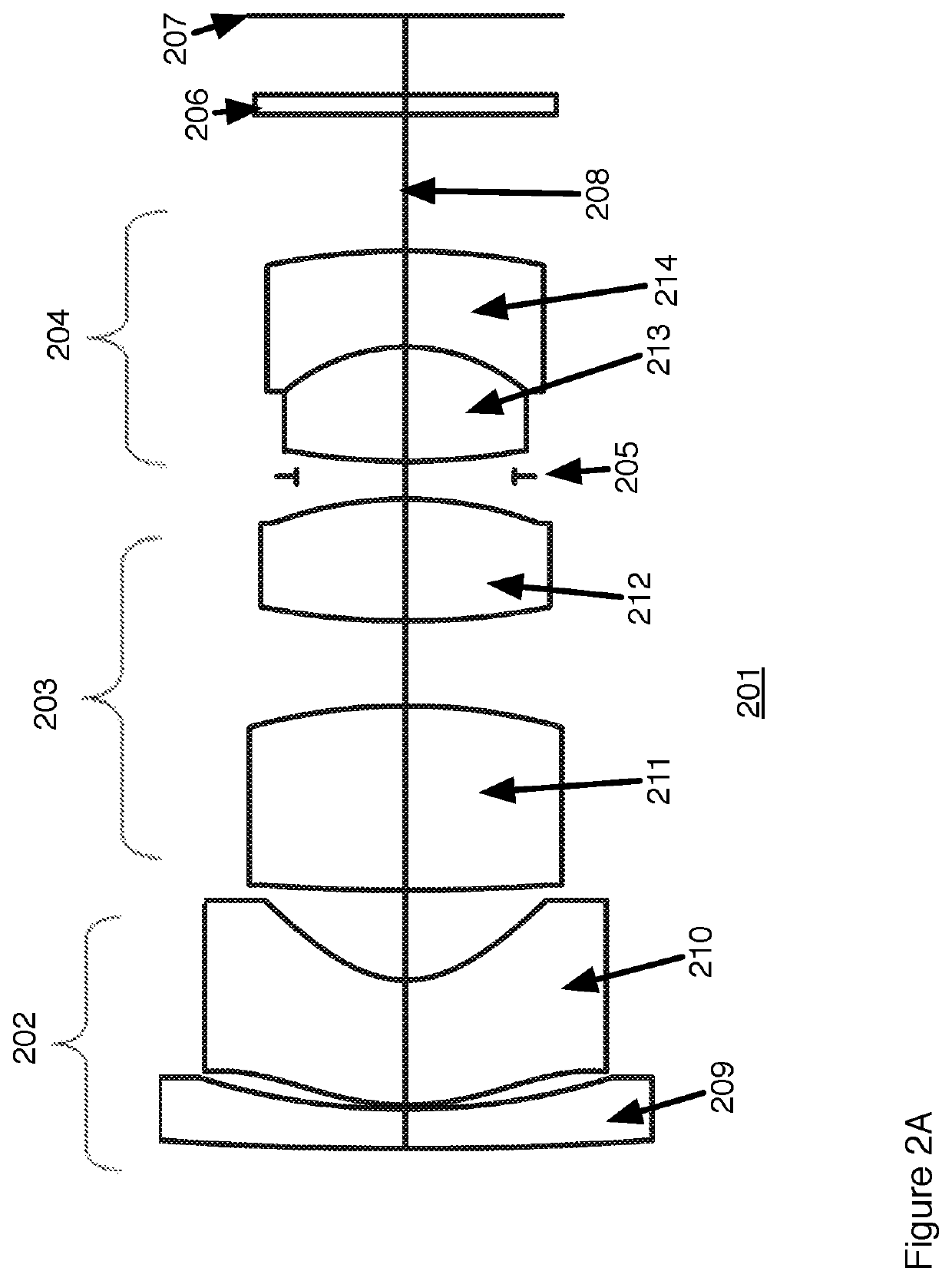
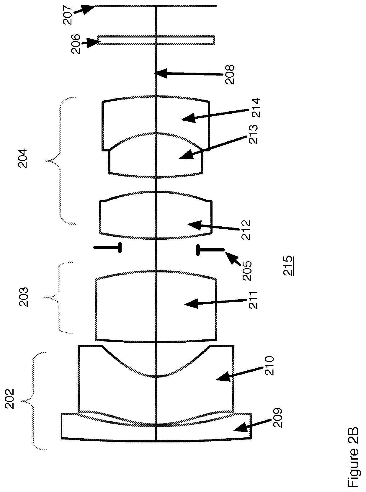
[0036]A second example of a fovea lens design uses the design as shown in FIG. 2. The 1st group comprises two elements 209, 210. The second lens element 210 is the aspherical element having surfaces S3 and S4. Both lens elements in the first group have negative power. Two elements 211, 212 are in the second group 203. Two elements 213, 214 are the third group 204. All elements in group 2 and 3 are spherical. This design has a field angle of + / −60° with a relative aperture of F / 1.6.
[0037]
TABLE 2ALens parameters for Example 2 according to FIG. 2SurfaceTypeRadiusThicknessNdAbbe#DiameterConic 1SPHERICAL90.851.001.729164,54.6712.490.00 2SPHERICAL17.470.1010.460.00 3ASPHERICAL6.383.151.809995,41.0010.17−2.54 4ASPHERICAL2.602.267.13−1.10 5SPHERICAL48.524.651.903663,31.427.290.00 6SPHERICAL−14.622.147.920.00 7SPHERICAL18.953.081.592824,68.627.310.00 8SPHERICAL−9.570.576.740.00STOSPHERICALInfinity0.385.520.0010SPHERICAL16.422.881.696800,55.535.880.0011SPHERICAL−4.762.431.846666,23.796.130.00...
example 3
[0039]A third example of a fovea lens design uses the design as shown in FIG. 3. The 1st group comprises two elements 309, 310. The second lens element 310 is the aspherical element having surfaces S3 and S4. Both lens elements in the first group have negative power. Two elements 311, 312 are in the second group 303. Three elements 313, 314, 315 are the third group 304. All elements in group 2 and 3 are spherical. This design has a field angle of + / −60° with a relative aperture of F / 1.6.
[0040]
TABLE 3ALens parameters for Example 3 according to FIG. 3SurfaceTypeRadiusThicknessNdAbbe#DiameterConic 1SPHERICAL84.730.981.5081.5913.120.00 2SPHERICAL11.030.0610.090.00 3ASPHERICAL4.572.571.7749.249.87−4.38 4ASPHERICAL2.322.577.35−0.77 5SPHERICAL−36.282.871.8840.817.360.00 6SPHERICAL−11.312.527.740.00 7SPHERICAL25.923.821.5968.626.630.00 8SPHERICAL−9.430.946.100.00STOSPHERICALInfinity0.095.350.0010SPHERICAL13.291.421.5968.625.620.0011SPHERICAL−35.740.095.870.0012SPHERICAL26.152.261.5081.595.9...
PUM
 Abstract
Description
Claims
Application Information
 - R&D
- Intellectual Property
- Life Sciences
- Materials
- Tech Scout
- Unparalleled Data Quality
- Higher Quality Content
- 60% Fewer Hallucinations
Browse by: Latest US Patents, China's latest patents, Technical Efficacy Thesaurus, Application Domain, Technology Topic, Popular Technical Reports.
© 2025 PatSnap. All rights reserved.Legal|Privacy policy|Modern Slavery Act Transparency Statement|Sitemap|About US| Contact US: help@patsnap.com


