
Sparsity-aware adaptive feedback cancellation

a feedback cancellation and adaptive technology, applied in repeater circuits, instruments, line-transmission details, etc., can solve problems such as distortion at the input, many fxlms systems and methods may be biased, and many lms systems and methods may be slow to adap

Active Publication Date: 2021-01-26
RGT UNIV OF CALIFORNIA
View PDF5 Cites 0 Cited by
  • Summary
  • Abstract
  • Description
  • Claims
  • Application Information

AI Technical Summary

Benefits of technology

These algorithms achieve better adaptation performance and stability, with improvements of up to 5 dB in signal-to-interference ratio, and are not sensitive to the choice of sparsity parameter p, making them suitable for quasi-sparse acoustic feedback paths in applications like hearing aids.

Problems solved by technology

In many current devices and systems comprising inputs such as microphones and outputs such as speakers, acoustic feedback from the output causes distortion at the input, especially when the output is an amplified version of the input.
However, estimates produced by many LMS systems and methods may be biased due to correlation between the input signal and a feedback signal.
However, many FXLMS systems and methods may be slow to adapt across highly time-varying feedback paths.
However, computational complexity may be high in many PEM systems and methods.
However, many NLMS systems and methods may become unstable for correlated signals such as tonal signals in the input.
Many NLMS systems and methods may not be able to provide high adaptation speed and maintain a low steady-state error simultaneously.
However, many PNLMS systems and methods may not improve feedback cancellation on channels that are quasi-sparse.
When large amplification is desired, many PNLMS systems and methods may be slow to adapt to varying feedback paths.

Method used


Image

  • Sparsity-aware adaptive feedback cancellation
  • Sparsity-aware adaptive feedback cancellation
  • Sparsity-aware adaptive feedback cancellation

Examples


Embodiment Construction

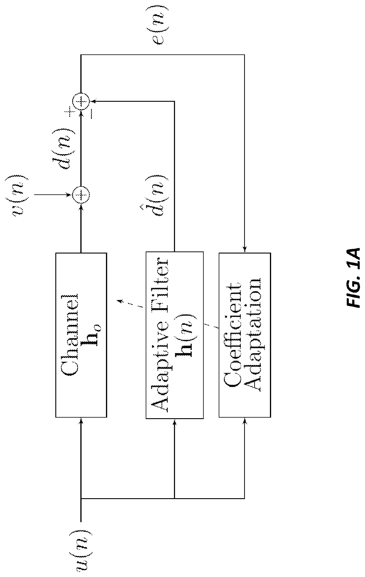
[0027]Systems and methods according to present principles are directed to improved algorithms employing special LMS methods that employ updating functionality. Two examples are provided below, although other examples will also be understood given the description that follows, including the figures and claims. The examples are in the field of adaptive feedback cancellation and beamforming.

[0028]Adaptive filters have been a research topic of interest for decades and have many potential applications such as in acoustic echo cancellation, active noise cancellation, channel equalization, speech processing, image processing, radar signal processing, among others. The most well-known adaptive filtering algorithms are the least mean squares (LMS) and the normalized LMS (NLMS) algorithms, which have been deployed in many practical applications due to their simplicity and effectiveness. In several applications, the impulse responses (IRs) that need to be identified are often sparse; i.e., whe...


PUM


Abstract

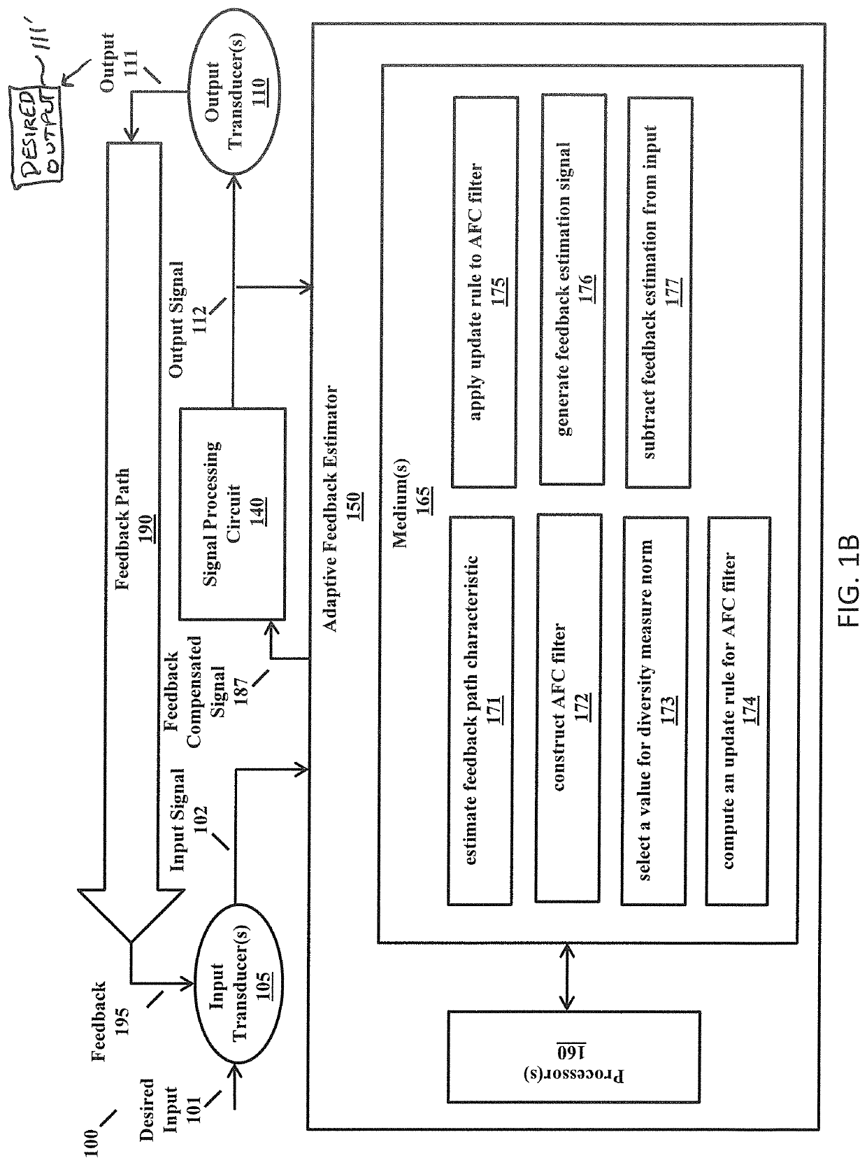
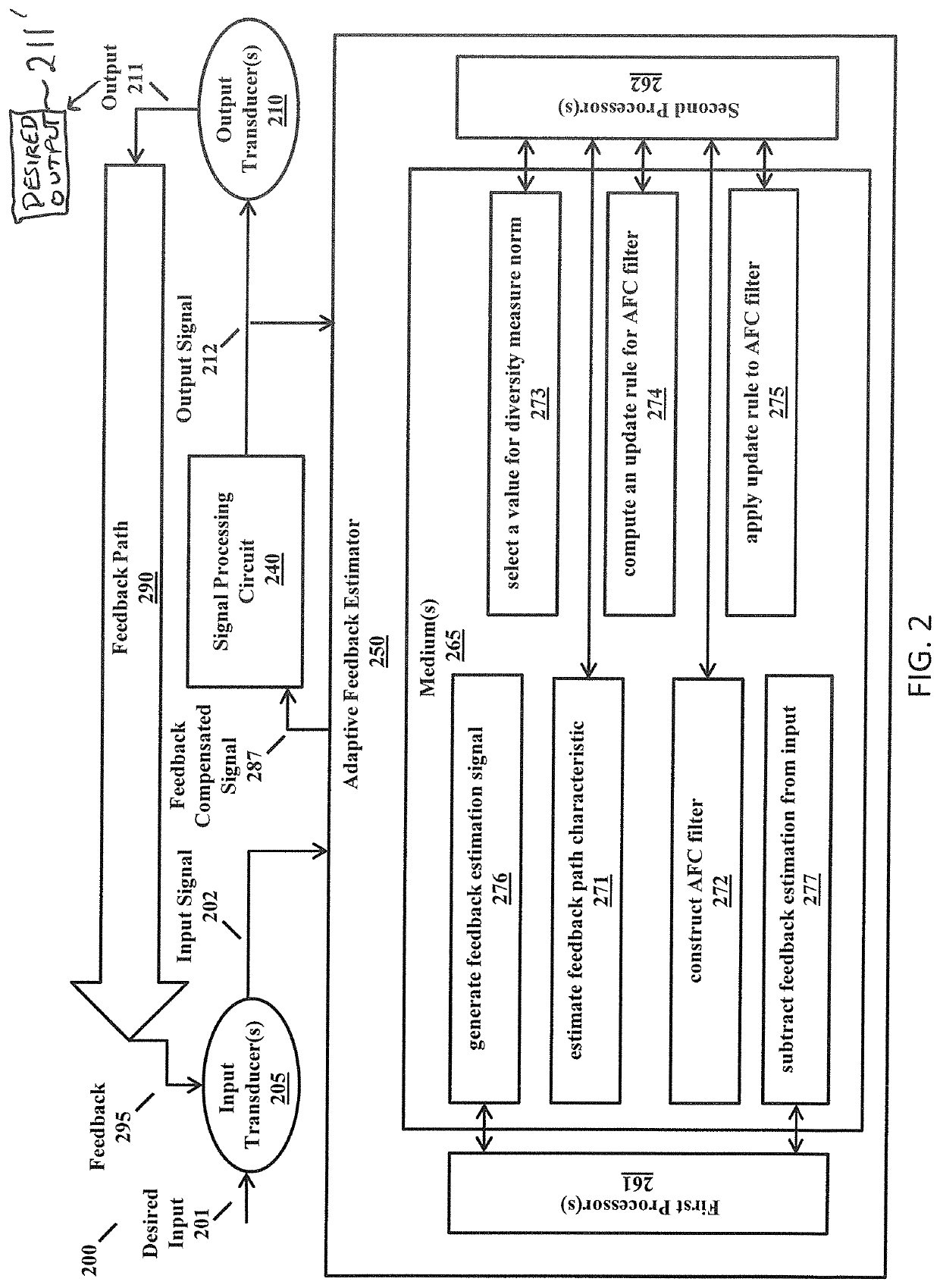
A signal processing device comprises: input transducer(s) configured to convert input(s) to an input signal; output transducer(s) configured to convert an output signal to output(s); a signal processing circuit configured to at least subtract a feedback estimation signal from the input signal to produce a feedback compensated signal; and an adaptive feedback estimator. The adaptive feedback estimator comprises processor(s) and machine readable medium(s) collectively comprising instructions configured to cause the processor(s) to: estimate feedback path characteristic(s); construct an adaptive feedback cancellation filter based at least in part on the feedback path characteristic(s); select a value for variable p in a diversity measure norm; compute an update rule for the adaptive feedback cancellation filter, the update rule based on the diversity measure norm; apply the update rule to the adaptive feedback cancellation filter; and generate the feedback estimation signal through employment of the adaptive feedback cancellation filter on the output signal.

Description

CROSS-REFERENCE TO RELATED APPLICATIONS[0001]This application is a National Stage in the US of PCT / US18 / 48171, filed Aug. 27, 2018 which claims the benefit of priority of U.S. Provisional Patent Application Ser. No. 62 / 550,166, filed Aug. 25, 2017, entitled “SPARSITY-AWARE ADAPTIVE FEEDBACK CANCELLATION”, owned by the assignee of the present application and herein incorporated by reference in its entirety.STATEMENT OF GOVERNMENT INTEREST[0002]This invention was made with Government support under DC015436—awarded by the National Institutes of Health. The Government has certain rights in the invention.BACKGROUND[0003]In many current devices and systems comprising inputs such as microphones and outputs such as speakers, acoustic feedback from the output causes distortion at the input, especially when the output is an amplified version of the input. Many adaptive feedback cancellation (AFC) systems and methods attempt to estimate variations in a feedback path so that an estimated feedba...

Claims


Application Information

Patent Timeline
Patent Type & Authority Patents(United States)
IPC IPC(8): H04B15/00G10K11/178
CPCG10K11/17854G10K11/17875G10K2210/3026G10K2210/3028H04B3/23H04M9/08H04M9/082H04B3/36
Inventor GARUDADRI, HARINATHLEE, CHING-HUARAO, BHASKAR
Owner RGT UNIV OF CALIFORNIA
Learn More