Devices and methods for direct-sampling analog time-resolved detection

a technology of time-resolved detection and analog signal, which is applied in the direction of optical radiation measurement, fluorescence/phosphorescence, radio frequency amplifier, etc., can solve the problems of requiring specialized electronic and modulated sources, modulated detectors, and current methods that are relatively expensive, and achieve cost-effective effects and increased instrumentation

Active Publication Date: 2021-02-02
RAGAN TIMOTHY M +1
View PDF34 Cites 0 Cited by
  • Summary
  • Abstract
  • Description
  • Claims
  • Application Information

AI Technical Summary

Benefits of technology

[0026]In one specific exemplary embodiment, the sampling device of the present invention is used for data analysis of photon migration. The sampling device includes: a photomultiplier tube for detecting an analog signal of a response reflected from a tissue sample which has been excited by a laser or other source. The analog-to-digital converter samples the analog signal generated by the excited tissue sample, and is received directly from the photomultiplier tube, and converted into a digital signal. A logic circuit, for example, a programmable gate array, is provided and coupled to the ADC for processing the digital signal received from the ADC. Here, the sampling rate of the converter is faster than the time of flight or phase delay of the response, and the logic circuit is capable of analyzing the digital signal continuously acquired from the ADC such that data analysis is obtained. The processing may include any one of a Fourier transform function, a Fast Fourier transform function, an X function, a Y function or a Z function such that various components of the analysis may be obtained, stored and displayed.
[0028]The subject invention has a number of advantages over known devices and methods. Previously, when sampling the harmonic content of the signal from the sample, there were three basic approaches: direct sampling, but with no streaming; heterodyning and homodyning. For heterodyne and homodyning, the detector (usually a PMT or CCD) had to be modulated at a frequency comparable to the illumination frequency of the light source used to investigate the sample. The resulting signal from the hetero / homodyning operation had a much lower frequency but required increased instrumentation and handling of the resultant data throughput. Thus, these hetero / homodyning introduce a range of drawbacks, among which are added cost, duty cycle losses in the detector (at least 50% loss in sensitivity), and the introduction of noise into the system by the RF modulation source. The subject invention overcomes these disadvantages by sampling the signal directly, analyzing the sampled data on the fly to reduce it to a manageable rate, and streaming the reduced data continuously to a recording device. Thus, it obtains desired data analysis in reduced form in a more cost effective and time efficient manner.

Problems solved by technology

However, the traditional frequency-domain electronics operating in the radio frequency range require gain modulated detectors, radio frequency amplifiers, and are not a simple addition to existing laser confocal microscopes.
Whatever approach is utilized, current methods are relatively expensive, and require specialized electronic and modulated sources.
Thus, a complication of traditional FD measurements is that it is not possible to measure the output of the detector, e.g. a photomultiplier tube (PMT), directly.
The situation is even worse if multiple frequencies are used to modulate the PMT as the duty cycle is reduced further.
A second disadvantage of these conventional techniques arises from the modulation.
While PMTs are nearly noiseless amplifiers, the radio frequency (RF) circuits and amplifier used for mixing introduce significant noise into FD measurements.
It is a major source of noise and reduces the overall sensitivity of traditional FD measurements.
This is due to the relatively slow electronics of the TCSPC method—the dead time of the instrument limited the rate at which photon could be processed.
In particular, the FLI data shown demonstrates that the TCSPC method is unable to handle bright regions in FLI image.
However, most common fluorophores exhibit spectra with a long\red emission tail, and quantitative measurements of more than three dyes become difficult.
Despite the useful information that these measurements could provide, a limited number of reports describe the implementation of combined lifetime and spectral imaging set-ups.
Although these two set-ups provide a well resolved emission spectrum and good lifetime quantification, they require a large emitted photon flux because of the poor quantum efficiency of the detection.
However, the time correlation of each photon takes time and leads to a dead time after each photon detection.
As a result, this is a severe limitation for the correct lifetime measurements at high count rates.
This set-up suffers from the same problem as the previous one.
The time needed for the detection is long.
While those limitations are mainly technical and could be circumvented by using multiple TCSPC cards, a system with sixteen independent time correlators has never been demonstrated and would be quite costly.

Method used


Image

  • Devices and methods for direct-sampling analog time-resolved detection
  • Devices and methods for direct-sampling analog time-resolved detection
  • Devices and methods for direct-sampling analog time-resolved detection

Examples


Embodiment Construction

[0045]Preferred embodiments of the present invention are described below with reference to the accompanying drawings, in which like reference numerals represent the same or similar elements.

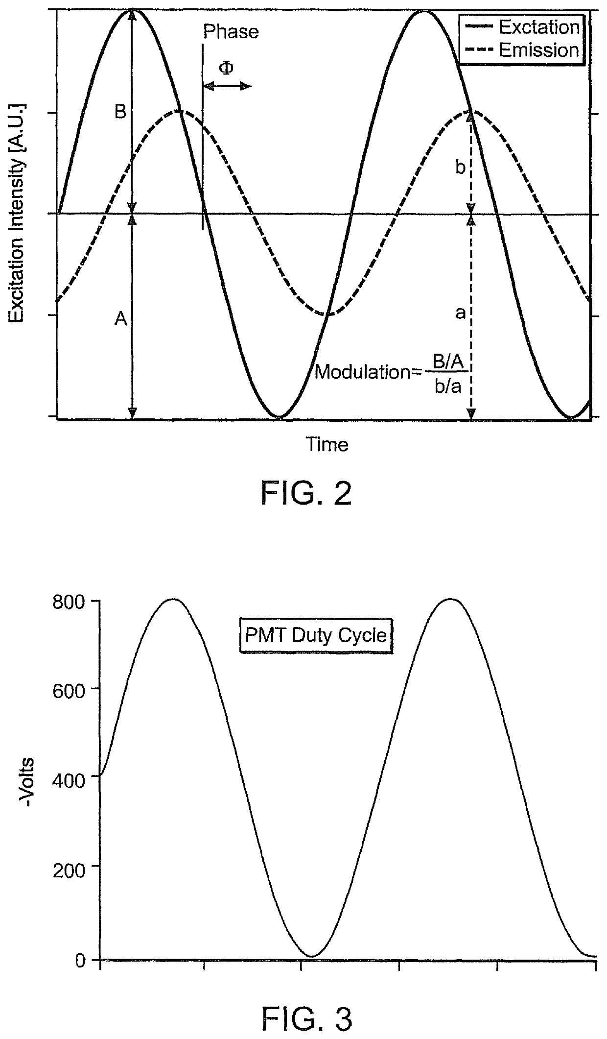
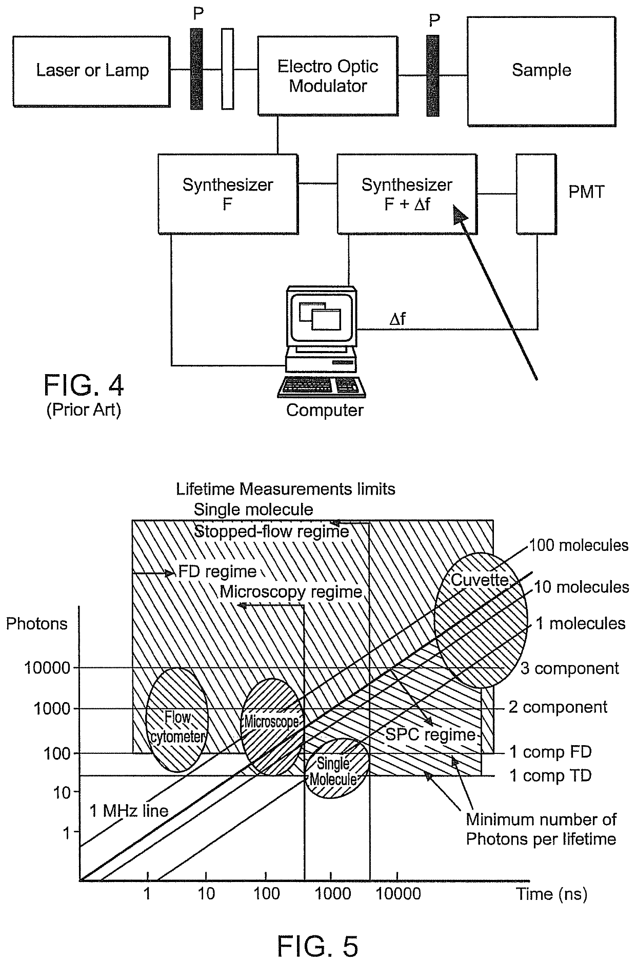
[0046]The subject invention provides an improved method for time-resolved detection that combines the dynamic range of frequency domain (FD), the sensitivity of time-correlated single photon counting (TCSPC), while being able to simultaneous acquire all harmonics in parallel in a single measurement. The subject invention achieves several advantages and benefits including, but not limited to: sensitivity improvement of a factor of two to four over traditional frequency domain approaches, simultaneous acquisition of all harmonics; high speed acquisition faster than the both the frequency domain and TCSPC; the ability to handle high signal levels; and low cost and scalability.

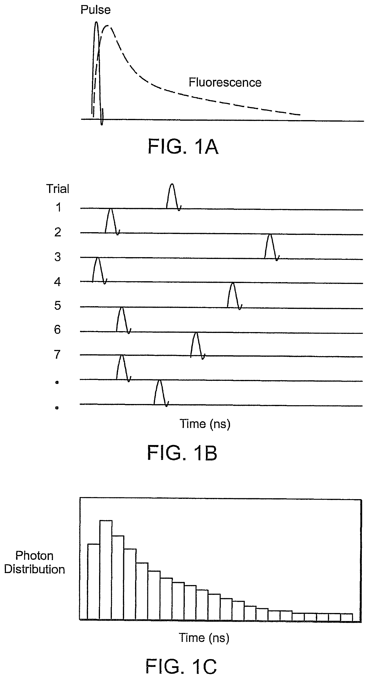
[0047]According to the subject invention, in a fluorescence application, for example, a signal is sampled faster than the dec...


PUM

PropertyMeasurementUnit
illumination frequencyaaaaaaaaaa
frequencyaaaaaaaaaa
timeaaaaaaaaaa

Abstract

Devices and methods for sampling an analog signal to perform data analysis are disclosed. The sampling devices and corresponding methods include a detector module that measures a response generated from a sample, an analog to digital converter that samples the analog signal, received from the detector module, and converting it into a digital signal, a sampling rate of the converter being faster than the response of the sample; and a logic circuit coupled to the converter that processes the digital signal in a frequency domain to generate a reduced digital data signal, the logic circuit processing the digital signal acquired from the converter to generate a continuous data transfer to a processing system.

Description

CROSS-REFERENCE TO RELATED APPLICATIONS[0001]This application is the national phase application pursuant to 35 U.S.C. § 371 of International Application No. PCT / US2009 / 060731, filed Oct. 14, 2009, which claims the benefit of priority of Provisional Patent Application No. 61 / 105,402, filed Oct. 14, 2008. These applications are hereby incorporated herein by reference in their entireties.BACKGROUND OF THE INVENTION[0002]1. Field of the Invention[0003]The subject invention relates to devices and methods for sampling an analog signal outputted from a detector in order to perform data analysis. More particularly, the present invention relates to devices and methods for a time-resolved approach that employs direct, high-speed sampling of the analog output of a detector, to capture harmonic content of the signal, without the need to modulate the detection system.[0004]2. Description of the Related ArtTime-Resolved Measurements[0005]Time-resolved measurements in biomedical science play a vit...

Claims


Application Information

Patent Timeline
Patent Type & Authority Patents(United States)
IPC IPC(8): G01N21/00G01N21/64G01N21/65
CPCG01N21/6408G01N21/6428G01N21/6458G01N2021/653G01J3/2889G01J3/2803G01J3/4406
Inventor RAGAN, TIMOTHY M.SUTIN, JASON D.
Owner RAGAN TIMOTHY M
Why Eureka
Try Eureka