Heat resistant descent controller

a descent controller and heat resistance technology, applied in the direction of building rescue, braking elements, brake types, etc., can solve the problems of heat generated in the descent controller device, the descent controller and the rope individually and together generate significant heat, and the buildup of material in the descent controller

Active Publication Date: 2021-02-16
TECH SAFETY LINES
View PDF26 Cites 7 Cited by
  • Summary
  • Abstract
  • Description
  • Claims
  • Application Information

AI Technical Summary

Benefits of technology

[0008]It is an object of the present disclosure to provide a new and improved load lowering descent controller of the type embodying a fixed cylindrical body or capstan about which a rope or cable is turned. Another object of the present disclosure is to provide a descent controller of the foregoing character that may be actuated for lowering a load such as an unconscious user or equipment. A further object of the present disclosure is to provide a descent controller of the foregoing character having a compact and robust design. Still another object of the present disclosure is to provide a descent controller wherein the operating components are substantially enclosed with a vented sleeve. A further object of the present disclosure is to provide a descent controller having the foregoing characteristics, which enables the user to adjust the mechanical advantage of the device. A further object of the present disclosure is to provide vents in a sleeve or protective sleeve to prevent the rope from generating excessive heat during a descent. The sleeve or protective sleeve can be manufactured through additive manufacturing, injection molding, milling, or other manufacturing techniques.
[0011]A bias member is disposed within the counterbore and between the plunger bottom portion and the housing. The bias member urges the plunger toward a position for wedging the rope in the narrow end of the tapered slot. An outer sleeve is secured to the plunger top portion for use in sliding the plunger against the force of the biasing spring to release the rope from the narrow end of the tapered slot. The sleeve defines a housing substantially enclosing the plunger, spring, friction cylinder and the rope wrapped therearound. The lower portion of the sleeve may also include a longitudinally extending slot therein of sufficient width for freely receiving the rope. Means are provided on the lower end of the housing for engagement with a load support. The descent controller supports a load on the rope and, upon sliding movement of the sleeve, provides for a controlled descent of descent controller and the supported load along the rope.
[0012]In another aspect of the disclosure, the controller can be secured at an elevated position and actuated at that point to lower a rope-supported load. The present disclosure provides a descent controller that substantially encloses the working components. Additionally, the descent controller can use parts that are robust in construction while requiring only a fraction of the length of some known controllers.

Problems solved by technology

One problem that arises with longer rope deployments is the heat that is generated in the descent controller device upon descent of a desired distance by a user.
As a user brakes and / or controls his or her descent, the descent controller and rope individually and together generate significant heat.
In some cases, the heat generated can exceed 300° F. As heat is generated, coatings and rope materials such as wax, and / or nylon begin to melt causing a buildup of this material within the descent controller.
The buildup can cause additional heat to be generated from the material to material contact (wax on wax contact) that generates increased friction and heat.

Method used


Image

  • Heat resistant descent controller
  • Heat resistant descent controller
  • Heat resistant descent controller

Examples


Embodiment Construction

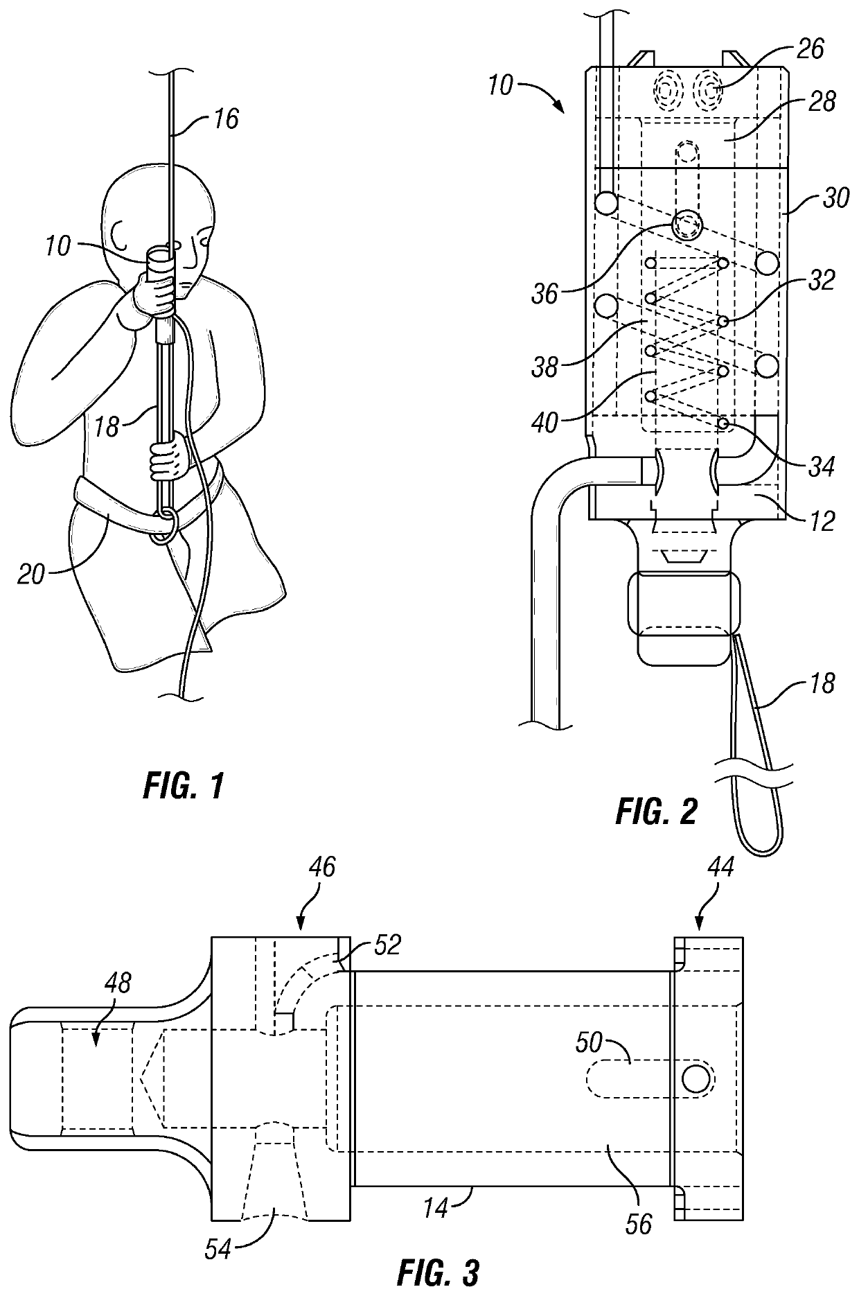
[0032]One embodiment of a descent controller 10 of the present disclosure is shown in FIGS. 1, 2 and 3. The descent controller comprises a housing 12 including a longitudinally oriented capstan 14 such as a cylinder shaft or drum about which a length of rope or line 16 is wound. The number of turns of rope is the principal determinate of the capstan ratio or mechanical advantage enabling the user or load to descend slowly along the fixed rope as the rope hangs from the elevated point. A user can change the number of turns of rope wound around the capstan to change the mechanical advantage and thereby the descent speed. The rope is secured at one end at an elevated point (not shown) above the ground, and hangs downwardly to the ground or a lower platform (not shown). The descent controller is mounted on the rope to enable the descent controller and user or a load to descend slowly and controllably along the fixed length of rope from the elevated point to the lower point, whether the ...


PUM


Abstract

A load lowering descent controller having a fixed cylindrical body or capstan about which a rope or cable is turned. The descent controller allows for lowering of the load at a controlled rate by adjusting the amount of friction between the controller and the rope or cable as a function of rope or cable turning and relative contact with rope or cable engagement surfaces in the controller. The fixed cylindrical body or capstan is surrounded by a vented sleeve to prevent the rope from becoming heated and to prevent the user from being injured.

Description

CROSS-REFERENCE TO RELATED APPLICATION[0001]Applicant incorporates herein by reference U.S. Pat. No. 7,131,515 B2; U.S. application Ser. No. 10 / 251,090; and U.S. Provisional Patent Application No. 60 / 324,756. This disclosure is a non-provisional of U.S. Design patent application Ser. Nos. 29 / 709,731, 29 / 709,729 and 29 / 709,730 filed on Oct. 16, 2019 and a non-provisional conversion of U.S. Provisional Patent Application Ser. No. 62 / 834,782, filed Apr. 16, 2019, the entirety of which is incorporated herein by reference in its entirety for all purposes.BACKGROUNDTechnical Field[0002]The present disclosure relates to a descent controller. More particularly, and not by way of limitation, the present disclosure is directed to an apparatus, system and method for a heat resistant descent controller.Background[0003]This background section is intended to provide a discussion of related aspects of the art that could be helpful to understanding the embodiments discussed in this disclosure. It i...

Claims


Application Information

Patent Timeline
Patent Type & Authority Patents(United States)
IPC IPC(8): A62B1/14F16D63/00
CPCA62B1/14F16D63/008F16D65/0979F16D55/22
Inventor DICKSON, JOHNNY
Owner TECH SAFETY LINES
Why Eureka
Try Eureka