Polarity-reversal protection arrangement, method for operating the polarity-reversal protection arrangement and corresponding use

A protection device and reverse polarity technology, which is applied in emergency protection circuit devices, emergency protection devices with automatic disconnection, circuit devices, etc., can solve the problem of inability to control the feedback of the vehicle power grid, the combination of the two modes, and no self-test /Diagnostic functions and other issues to achieve the effect of saving space and resources, compact and robust product design, and reducing heat loss

Active Publication Date: 2020-06-12
CONTINENTAL AUTOMOTIVE TECH GMBH
View PDF11 Cites 0 Cited by
  • Summary
  • Abstract
  • Description
  • Claims
  • Application Information

AI Technical Summary

Problems solved by technology

[0006] - The two modes cannot be used in combination
[0007] - No controlled feedback to the on-board electrical network
[0008] - No self-test / diagnostics in linear mode

Method used


Image

  • Polarity-reversal protection arrangement, method for operating the polarity-reversal protection arrangement and corresponding use
  • Polarity-reversal protection arrangement, method for operating the polarity-reversal protection arrangement and corresponding use
  • Polarity-reversal protection arrangement, method for operating the polarity-reversal protection arrangement and corresponding use

Examples


Embodiment Construction

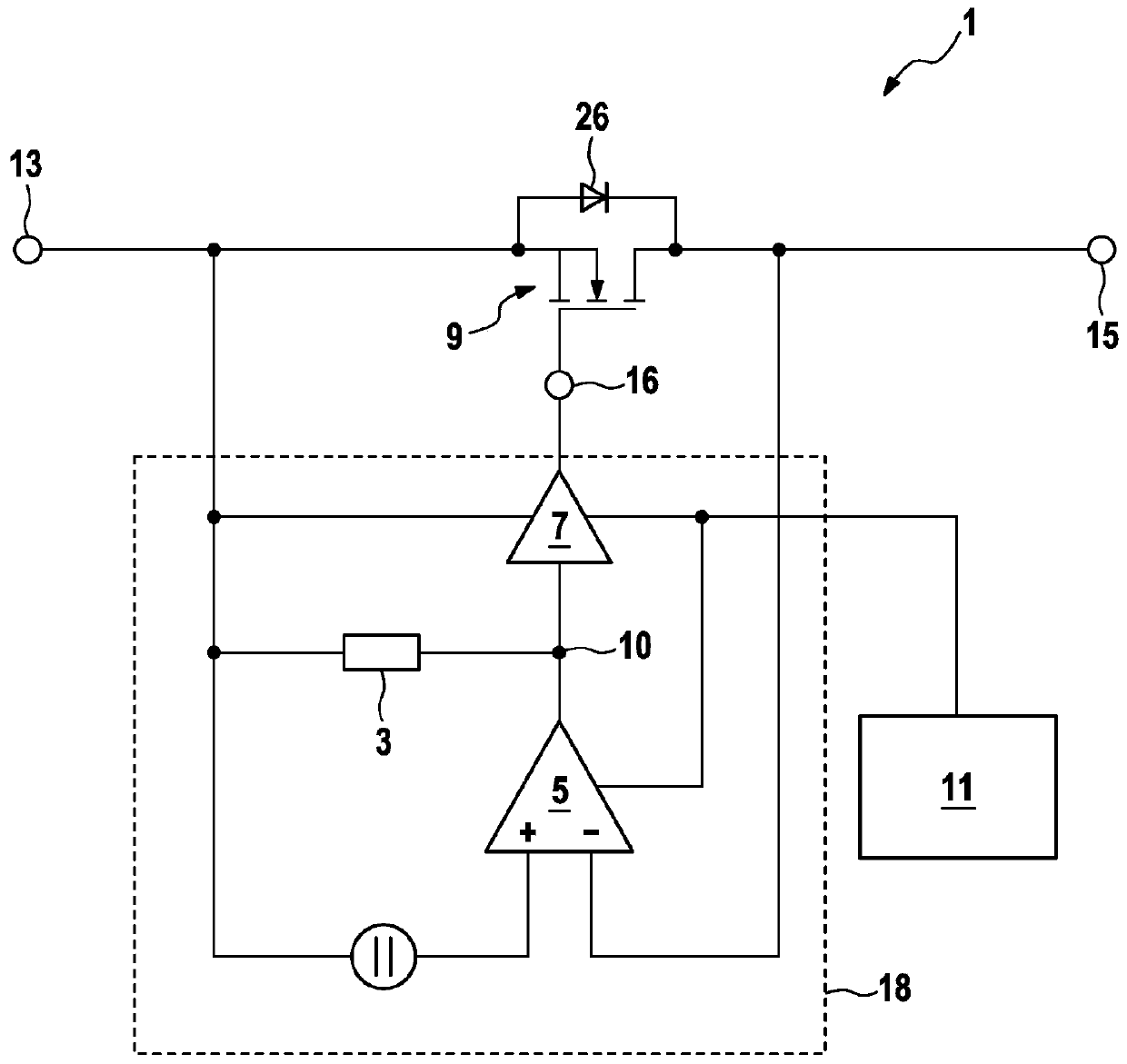
[0039] figure 1 A prior embodiment of a reverse polarity protection device 1 with an additional resistor 3 is shown. The reverse polarity protection device 1 has an amplifier circuit 5 , an output driver stage 7 and a transistor circuit 9 . The transistor circuit 9 is preferably designed as an N-MOS transistor. For this reason, the reverse polarity protection device 1 also includes a charge pump 11 . Alternatively, the transistor circuit 9 can also be designed as a P-MOS transistor, in which case the charge pump 11 can be omitted. Resistor 3 is connected to node 10 and first connection node 13 .

[0040]The reverse polarity protection device 1 is arranged between a first connection node 13 and a second connection node 15 . In particular, the transistor circuit 9 of the reverse polarity protection device 1 is arranged between a first connection node 13 (the so-called KL30 terminal) and a second connection node 15 (the so-called KL30B terminal). The first connection node 13...


PUM


Abstract

The invention relates to a polarity-reversal protection arrangement comprising a transistor circuit (9), an amplifier circuit (5) and an output driver stage (7), wherein the amplifier circuit (5) is connected to the output driver stage (7) and the output driver stage (7) is connected to the transistor circuit (9) and the transistor circuit (9) is arranged between a first connection node (13) and asecond connection node (15) of the polarity-reversal protection arrangement (1) so that an electrical connection between the first connection node (13) and the second connection node (15) can be produced or disconnected by means of the transistor circuit (9), wherein the output driver stage (7) is designed as a tri-state stage. The invention further relates to a method for operating the polarity-reversal protection arrangement (1) and to a corresponding use.

Description

technical field [0001] The invention relates to a reverse polarity protection device according to the preamble of claim 1 , a method for operating a reverse polarity protection device according to claim 6 and a reverse polarity protection device according to claim 9 Use of polarity protection devices. Background technique [0002] Control devices for motor vehicles are known from the prior art, in which energy is prevented from flowing back into the vehicle electrical system in order not to endanger the safety of the vehicle. A transistor is used for this, which does not allow a return current at the node to flow into the vehicle electrical system and protects the electronics of the control unit against negative voltages (reverse polarity protection function). [0003] In the so-called linear mode, transistors (especially FETs) are driven in such a way that they behave like ideal diodes. All known interfering pulses are filtered out by disconnecting the ECU load circuit fo...

Claims


Application Information

Patent Timeline
Patent Type & Authority Applications(China)
IPC IPC(8): H02H3/04H02H11/00
CPCH02H3/044H02H11/003H02H3/18B60R16/03G05F1/461
Inventor T·法赫布什
Owner CONTINENTAL AUTOMOTIVE TECH GMBH
Why Eureka
Try Eureka