
Optical inspection of surfaces open to different directions in a piece of material

a technology of optical inspection and open surface, which is applied in the direction of material analysis, instruments, drug compositions, etc., can solve the problems of high equipment cost, slow production, and heavy and bulky optical equipment consisting of ordinary lenses and/or mirrors, and achieve compact and robust design and excellent operational reliability.

Inactive Publication Date: 2012-01-10
EKSPANSIO ENG
View PDF11 Cites 0 Cited by
  • Summary
  • Abstract
  • Description
  • Claims
  • Application Information

AI Technical Summary

Benefits of technology

[0008]One of the chief advantages of the invention is that the arrangement of the invention allows imaging of all the other surfaces of a moving object, except the ends perpendicular to the direction of movement, using an electronic camera with a view to inspection and potential measurement of the surfaces. The invention also has the advantage of allowing such imaging using one single electronic camera, although two cameras can be used if desired, while the entire object is imaged by passing it once through an apparatus corresponding to the arrangement of the invention, given the substantially simultaneous imaging of all of the outer surfaces of the object by means of the invention. The invention has the further advantage of maintaining all the outer surfaces simultaneously within the depth of field of the electronic camera and also of eliminating the central perspective and replacing it with true planar projections. In addition, the apparatus implementing the arrangement of the invention has a compact and robust design and thus ensures excellent operational reliability.

Problems solved by technology

In telecentric objectives, the lens or concave mirror closest to the object should have a width equalling at least the object, and this results in heavy and bulky optical equipment consisting of ordinary lenses and / or mirrors.
This can obviously be done by means of four devices directed towards the upper surface, lower surface and lateral surfaces of the object, but this incurs high equipment costs.
Another option is turning the object and running it through the imaging area of a telecentric imaging unit four times. Firstly, such an arrangement is slow in terms of production and secondly, mutual positioning of the image data obtained on different sides of the object is problematic.

Method used


Image

  • Optical inspection of surfaces open to different directions in a piece of material
  • Optical inspection of surfaces open to different directions in a piece of material
  • Optical inspection of surfaces open to different directions in a piece of material

Examples


Embodiment Construction

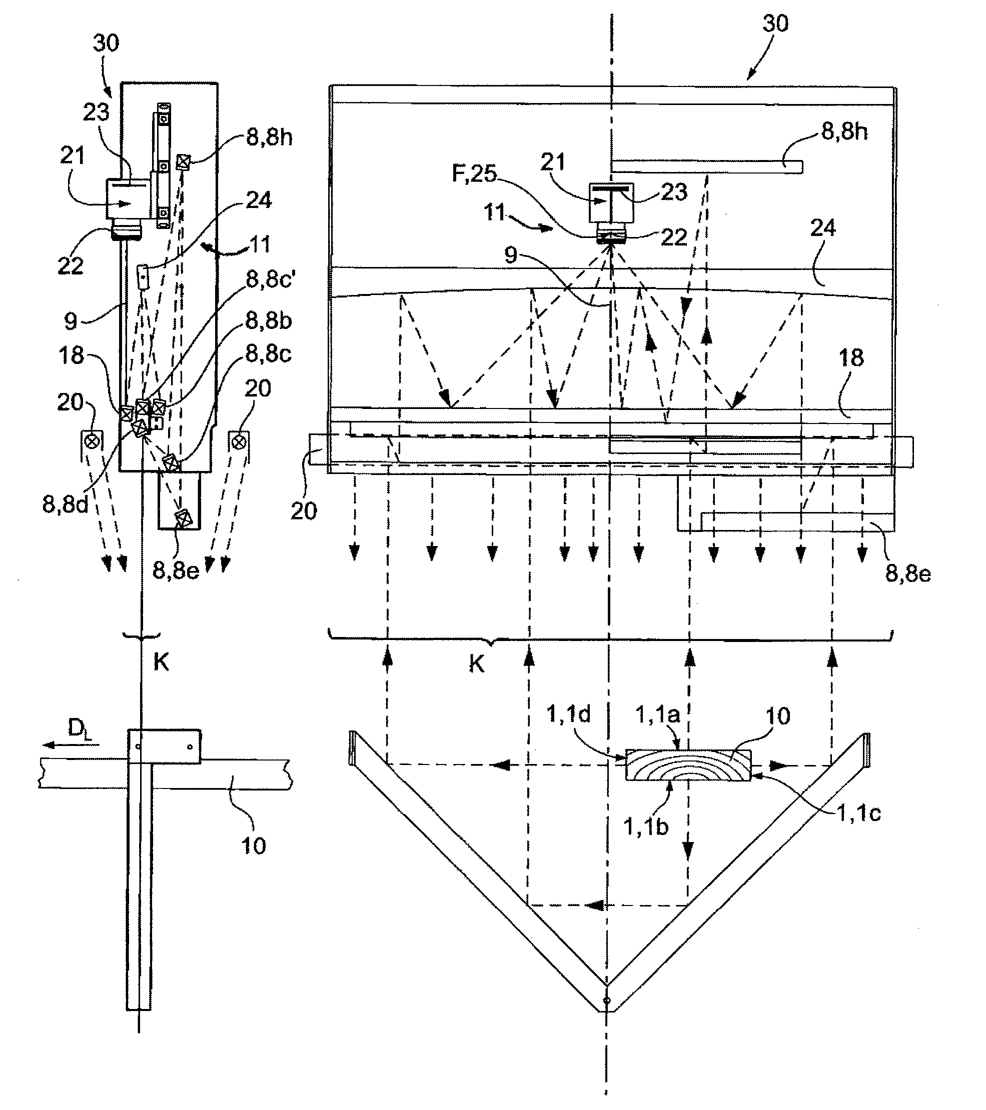
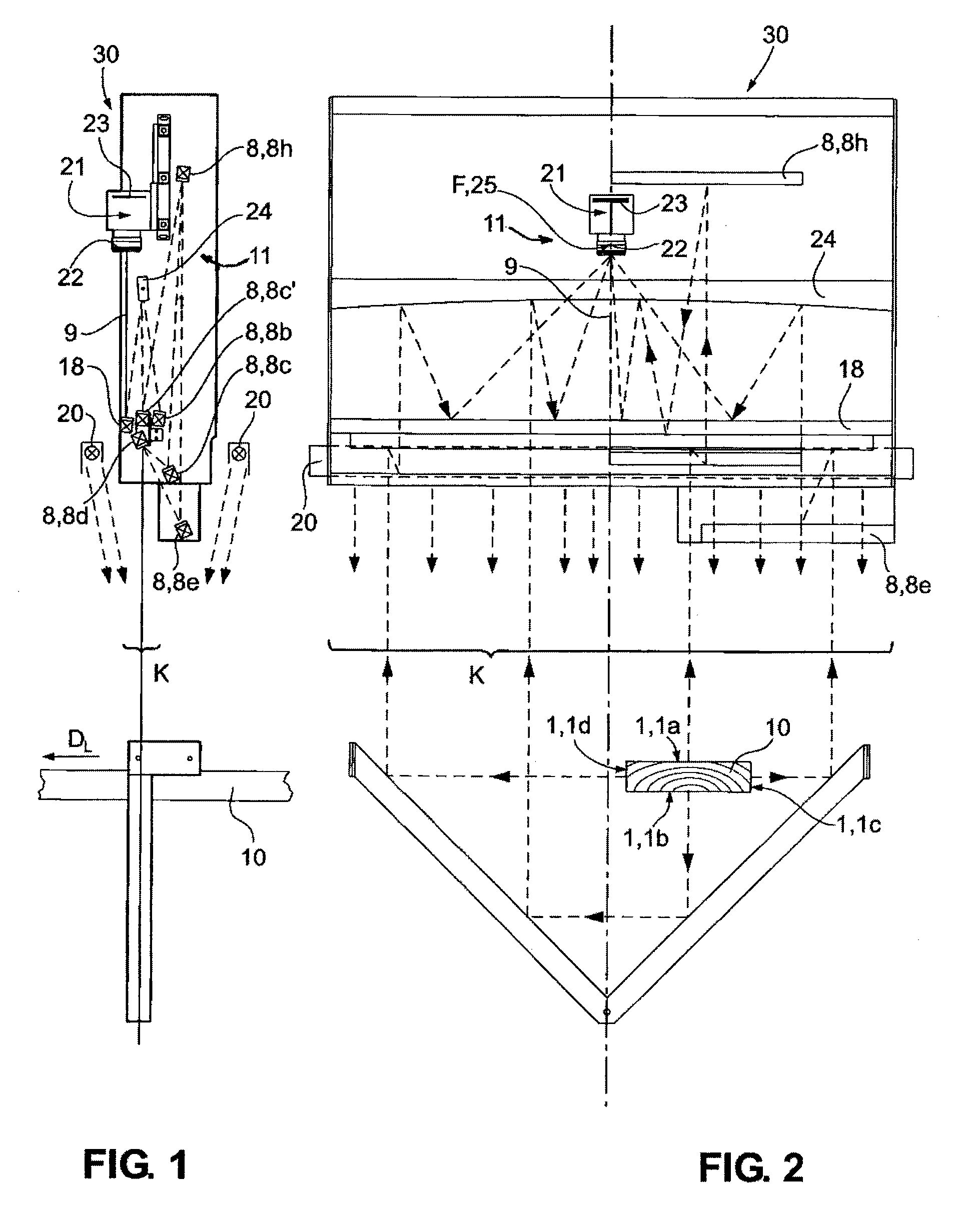
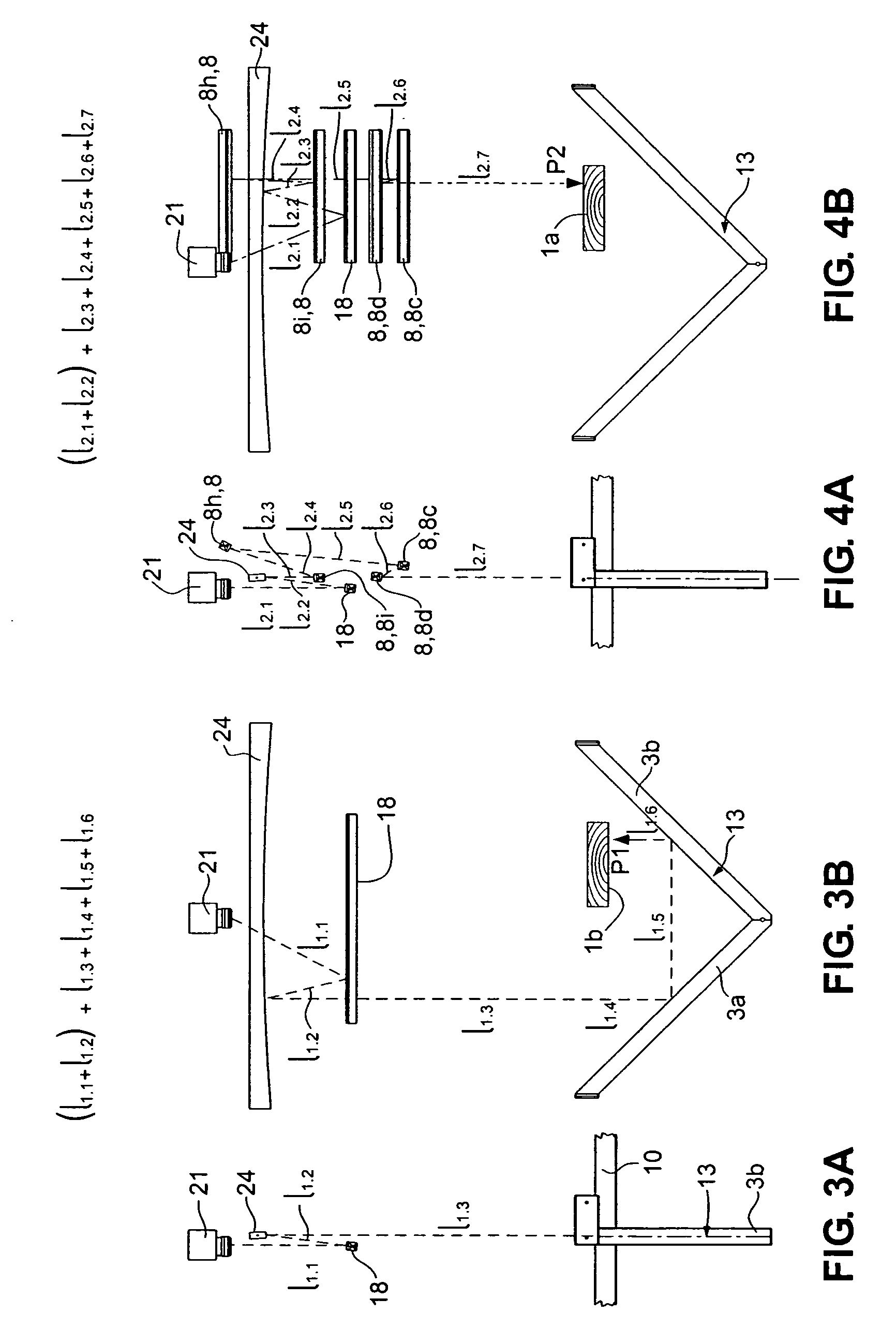
[0022]The figures illustrate a device for optical inspection of the open surfaces 1 of the profiles of objects 10, especially objects moving in the longitudinal direction, such as sawn goods or planed timber, but also objects of other materials, from at least two different viewing directions P1, P2. In this context, open surfaces 1 imply a surface visible from the outside and thus possible to inspect, but not e.g. the inside of pipes or hollow profiles, i.e. cavities. The open surfaces are generally referred to with reference numeral 1, which implies any open surface of an object, the specifying reference numerals implying the lateral surfaces 1c and 1d and the lower surface 1b and the upper surface 1a only in cases where it is necessary to make a difference between these. The objects move through the device of the invention in the direction of movement DL. The device of the invention comprises primarily the illuminating means 20 for illuminating the open surfaces of the object. The...


PUM

PropertyMeasurementUnit
angleaaaaaaaaaa
areaaaaaaaaaaa
imaging distancesaaaaaaaaaa

Abstract

The invention relates to a device for optical inspection of the open surfaces (19 of objects from at least two different viewing directions (P1, P2). The device comprises a telecentric imaging unit (11 or 12, an angle mirror (13) and auxiliary mirrors (8) within the area (K) of the telecentric imaging unit, between this and the object. The object is placed between the arms (3a, 3b) of the angle mirror (13) and the telecentric imaging unit is directed towards the combination of object and angle mirror. The auxiliary mirrors (8) have been oriented and positioned at intervals from the telecentric imaging unit such that the differences of distance of the viewing directions (P1 and / or P2 and / or P3 and / or P4) via the two arms (3a and 3b) of the angle mirror or via one arm (3a tai 3b) or not via the arms are compensated as they pass via the auxiliary mirrors.

Description

CROSS REFERENCE TO RELATED APPLICATIONS[0001]This application is for entry into the U.S. national phase under §371 for International Application No. PCT / FI05 / 000182 having an international filing date of Apr. 12, 2005, and from which priority is claimed under all applicable sections of Title 35 of the United States Code including, but not limited to, Sections 120, 363 and 365(c) and which in turn claims Priority under Section 119 to Finnish Patent Application No. 20040694 which was filed on May 18, 2004.TECHNICAL FIELD[0002]The invention relates to a device for optical inspection of open surfaces of objects from at least two different viewing directions, the device comprising: illuminating means (light or radiation source) for illuminating the open surfaces of the objects; sensor means (sensor) for detecting the light intensity reflected by different locations of the open surfaces of the objects and for converting the light into electronic form.BACKGROUND OF THE INVENTION[0003]A typ...

Claims


Application Information

Patent Timeline
Patent Type & Authority Patents(United States)
IPC IPC(8): G01N21/00G01BG01B11/04G01B11/24G01B11/30G01N21/84G01N21/88G01N21/898
CPCG01B11/04G01N21/8806G01N21/8986A61P29/00
Inventor PAAVOLA, JYRI
Owner EKSPANSIO ENG
Learn More