Infrared fluorescent coatings

a technology of infrared fluorescent coatings and coatings, applied in the field of cool building materials, can solve the problems of limited infrared reflectance of other specified dark colors, increased temperature, and dark colored building materials, etc., and achieve greater effective solar reflectance (esr), and greater effective solar reflectance (esr).

Active Publication Date: 2021-02-23
RGT UNIV OF CALIFORNIA +1
View PDF42 Cites 5 Cited by
  • Summary
  • Abstract
  • Description
  • Claims
  • Application Information

AI Technical Summary

Problems solved by technology

In a similar manner, the reflectance of other specified dark colors is limited because absorption in the visible is required to formulate a dark color.
However, dark colored building materials, facades, and roofs are susceptible to absorption of infrared (“IR”) radiation.
As a result, the structures exhibit increased temperatures and become quite hot, particularly on sunny days in warm and hot climates, rendering their occupants uncomfortable.
In addition, such buildings are then more expensive to operate and require more energy, since higher levels of air conditioning are required to maintain a certain level of comfort as compared to structures having lighter colors with higher reflectivity.
Similarly, transportation vehicles such as aircrafts or automobiles can suffer excessive solar heat gain when coated with dark colors and require more air conditioning to maintain comfortable climate control.
In addition, objects made with composites, such as fiber reinforced polymer composites, can suffer mechanical damage from overheating due to solar heat gain and often require lighter colors to maintain composite surface temperatures below a critical operating maximum.

Method used


Image

  • Infrared fluorescent coatings
  • Infrared fluorescent coatings
  • Infrared fluorescent coatings

Examples


example 1

Synthesis of Red Pigments Via Combustion Synthesis and Analyses

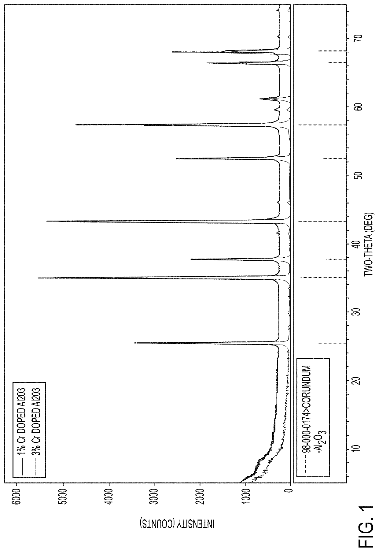
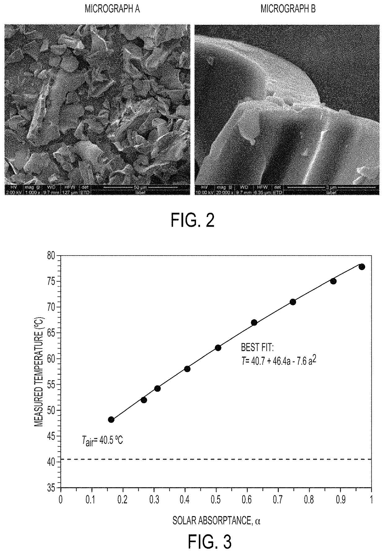
[0142]Samples of Al2O3 (4 g, 16 g, and 200 g) doped with 1 wt % Cr2O3 or 3 wt % of Cr2O3 were synthesized via a combustion synthesis method. Analytical testing was conducted on two samples of dark red pigments Al2O3 doped with 1 wt % Cr2O3 and Al2O3 doped with 3 wt % of Cr2O3. X-ray fluorescence (semi-quantitative) indicated that the elemental compositions of the pigments were close to their expected values. X-ray diffraction XRD patterns of the two samples showed the presence of α-Al2O3, which is the desired phase of Al2O3 for NIR fluorescence. In addition, the narrow peaks in the XRD patterns suggested the presence of large crystalline particles (FIG. 1). Scanning electron microscopy (SEM) was employed to observe the particle size and morphology of the pigment samples prepared by combustion synthesis (FIG. 2, micrograph B). Micrographs indicated the presence of large particles (FIG. 2, micrograph A). During the combust...

example 2

Testing Methods

[0143]Three calibration panels (whose spectral reflectance values were measured using a Perkin Elmer Lamda 900 UV-Vis-NIR spectrometer) were placed onto a support along with an experimental sample. The surface temperatures were measured with an IR thermometer and plotted versus time. The effective solar absorptance for the experimental sample was interpolated from the solar absorptance values for the calibrated samples. The effective solar reflectance (ESR) was then calculated using the formula: ESR=1−effective solar absorptance (a).

[0144]FIG. 3 shows a plot of the temperature rise when all of the standard reference samples are used at the same time. These measurements were taken on a clear summer day, near noon. They show that the sunlit temperature, as a function of spectrometer-measured solar absorptance a, is slightly non-linear. This shows that the basic function of temperature vs. absorptance a has negative curvature.

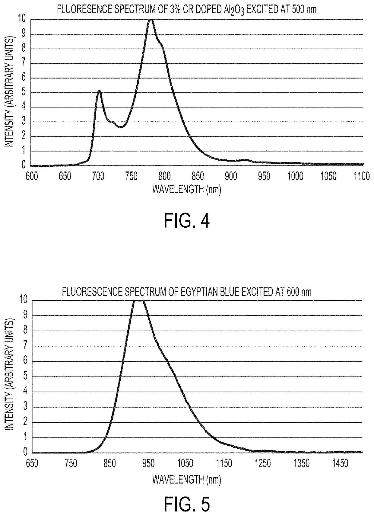
[0145]Measurement of the fluorescence of the ...

example 3

Coatings Including Red Pigment

[0147]Coatings based on PVDF including 500 g / m2 of Al2O3 doped with Cr2O3 pigments were synthesized via the combustion process described above (particle size of several microns). These coatings had a reflectance of 0.31 at 550 nm. Thinner coatings with 100 g / m2 of Al2O3 doped with Cr2O3 synthesized via the combustion process described above had a reflectance of 0.38 at 550 nm.

[0148]Additionally, Al2O3 doped with 1.5 wt % and 4.5 wt % Cr2O3 pigments with an average particle size of 650 nm were prepared. Egyptian blue pigments were also prepared with an average particle size of 650 nm. These pigments were included into a coating based on a PVDF film-forming resin. Effective solar reflectance (ESR) measurements were made on the coatings made using these pigments and are shown in Table 4. The substrates utilized for the evaluation of the coatings were aluminum substrates coated with a yellow chrome primer.

[0149]

TABLE 4ESR measurements for samplesSpectromete...


PUM

PropertyMeasurementUnit
particle sizeaaaaaaaaaa
wavelengthaaaaaaaaaa

Abstract

The present invention provides for a composition comprising a pigment, wherein the composition is suitable for coating a surface that is, or is expected to be, exposed to the sun. The pigment comprises particles that fluoresce in sunlight, thereby remaining cooler in the sun than coatings pigmented with non-fluorescent particles. The particles comprise solids that fluoresce or glow in the visible or near infrared (NIR) spectra, or that fluoresce when doped. Suitable dopants include, but are not limited to, ions of rare earths and transition metals. A coating composition includes: (i) a film-forming resin; (ii) an infrared reflective pigment; and (iii) an infrared fluorescent pigment different from the infrared reflective pigment. When the coating composition is cured to form a coating and exposed to radiation comprising fluorescence-exciting radiation, the coating has a greater effective solar reflectance (ESR) compared to the same coating exposed to the radiation comprising fluorescence-exciting radiation except without the infrared fluorescent pigment. A multi-layer coating including the coating composition, and a substrate at least partially coated with the coating composition is also disclosed. A method of reducing temperature of an article includes applying the coating composition to at least a portion of the article.

Description

STATEMENT OF GOVERNMENTAL SUPPORT[0001]The invention was made with government support under Contract Nos. DE-AC02-05CH11231 and DE-EE-0006347 awarded by the U.S. Department of Energy. The government has certain rights in the invention.FIELD OF THE INVENTION[0002]The present invention is in the field of cool building materials. The present invention also relates to a coating composition including a film forming resin, an infrared reflective pigment, and an infrared fluorescent pigment different from the infrared reflective pigment. The present invention also relates to a multi-layer coating composition, a coated substrate, and a method of reducing temperature of an article.BACKGROUND OF THE INVENTION[0003]Current work on cool materials (particularly for roofing) has focused on the basic idea to find various colored materials, such as coatings, tiles, roofing granules, etc., that stay cooler in the sun than conventional materials. White materials are usually best, but architects and b...

Claims


Application Information

Patent Timeline
Patent Type & Authority Patents(United States)
IPC IPC(8): C09D5/22C09D127/16C09D5/33B05D3/06B05D7/14B05D5/06C09K11/56C09K11/77C09K11/68C09D7/62C09K11/88C09D7/61C09K11/54C09D5/38C09D5/32C08K3/22C08K9/02C08K3/34
CPCC09D5/22B05D3/06B05D5/06B05D7/14C09D5/004C09D5/32C09D5/38C09D7/61C09D7/62C09D127/16C09K11/54C09K11/562C09K11/685C09K11/7704C09K11/7706C09K11/7772C09K11/7774C09K11/883C08K3/22C08K3/34C08K9/02C08K2003/2206C08K2003/2227C08K2003/2248C08K2003/2251C08K2201/014C09K11/77062C09K11/02C09K11/64
Inventor ZALICH, MICHAEL ANDREWBAXTER, MICHAEL F.BERDAHL, PAUL H.HELLRING, STUART D.STALKER, JEFFREY LYNN
Owner RGT UNIV OF CALIFORNIA
Why Eureka
Try Eureka