Cooling fan module

a cooling fan and module technology, applied in the direction of liquid fuel engines, lighting and heating apparatus, instruments, etc., can solve the problems of incorrect connection and cooling fan, and achieve the effect of convenient assembly and disassembly of the cooling fan modul

Active Publication Date: 2021-02-23
TAIWAN MICROLOOPS CORP
View PDF3 Cites 2 Cited by
  • Summary
  • Abstract
  • Description
  • Claims
  • Application Information

AI Technical Summary

Benefits of technology

[0005]The present invention provides a cooling fan module which uses an external connector electrically plugged in the fan connector to send a first signal and uses the external connector electrically plugged in the LED controller to send a second signal such that the required power for the fan body and the required signals for operation of the light emitting part are distributed together through a common external connector. In this way, the cooling fan module has only one external connector for external connection to achieve the advantages of easy assembly and reduced incorrect connection.
[0007]Based on the previous description, the fan frame provided with plural slits, a latching slot disposed on the bottom wall of each of the slits, the fan body having a supporting stand extending to form plural flexible arms, each of the flexible arms protruding a latch, the flexible arms being individually snap-fit to the corresponding slits, and the latches being individually snap-fit to the corresponding latching slots achieve the effects of easy assembly and disassembly of the cooling fan module.

Problems solved by technology

Thus, the cooling fan has to be equipped with two connectors for external connection, which causes the complicated assembly steps of the cooling fan and the incorrect connection thereof.

Method used


Image

  • Cooling fan module
  • Cooling fan module
  • Cooling fan module

Examples


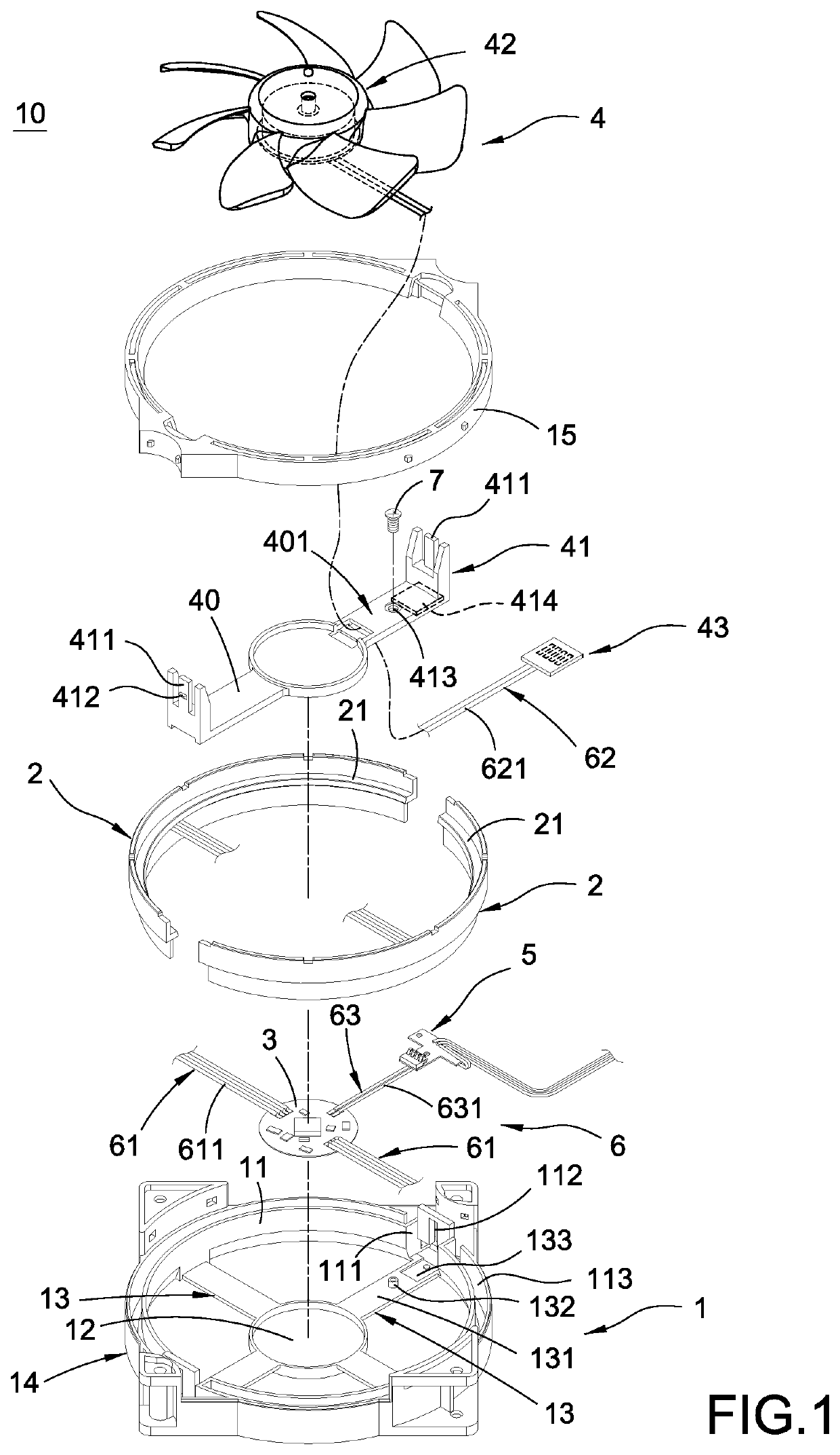
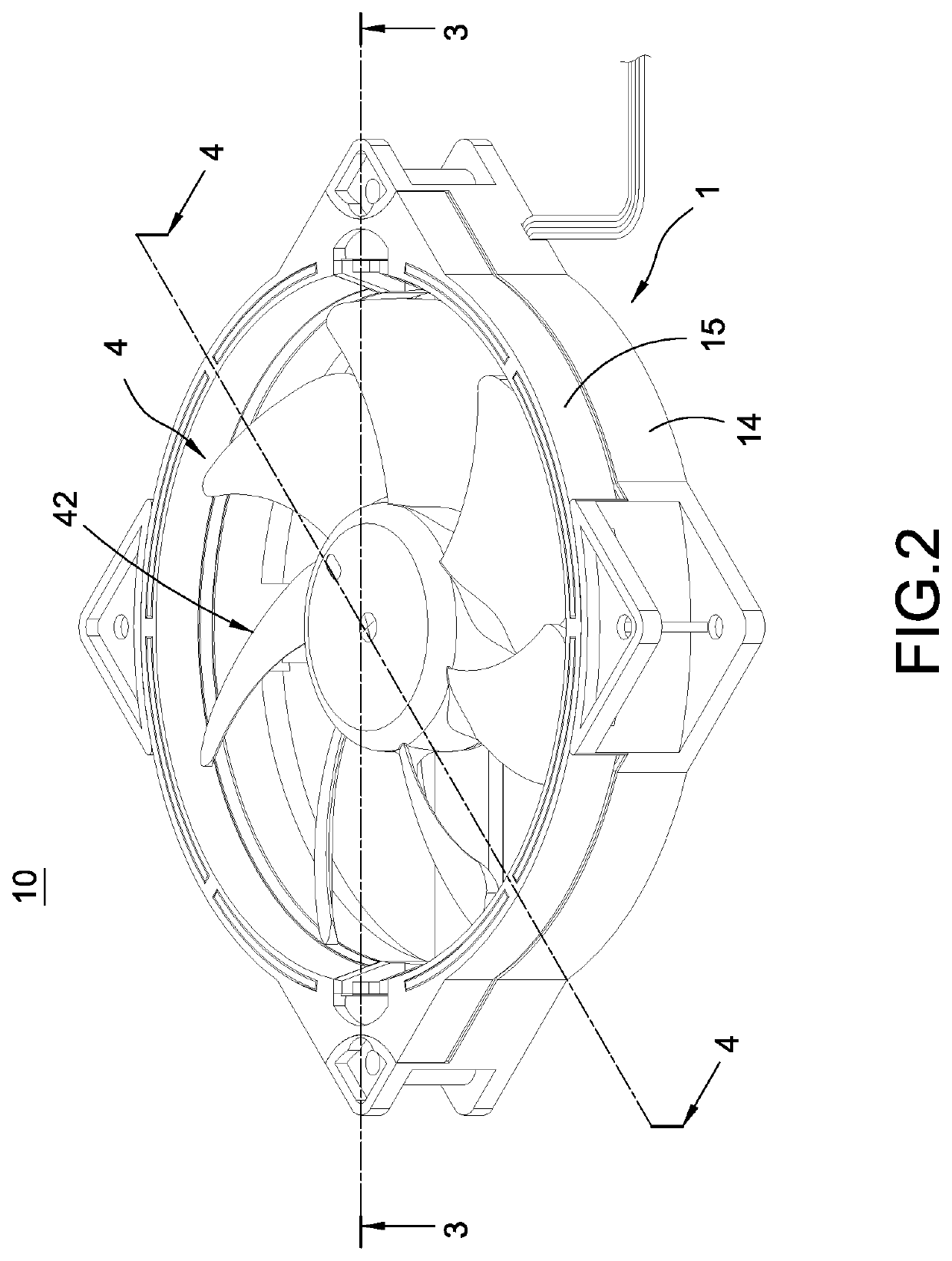
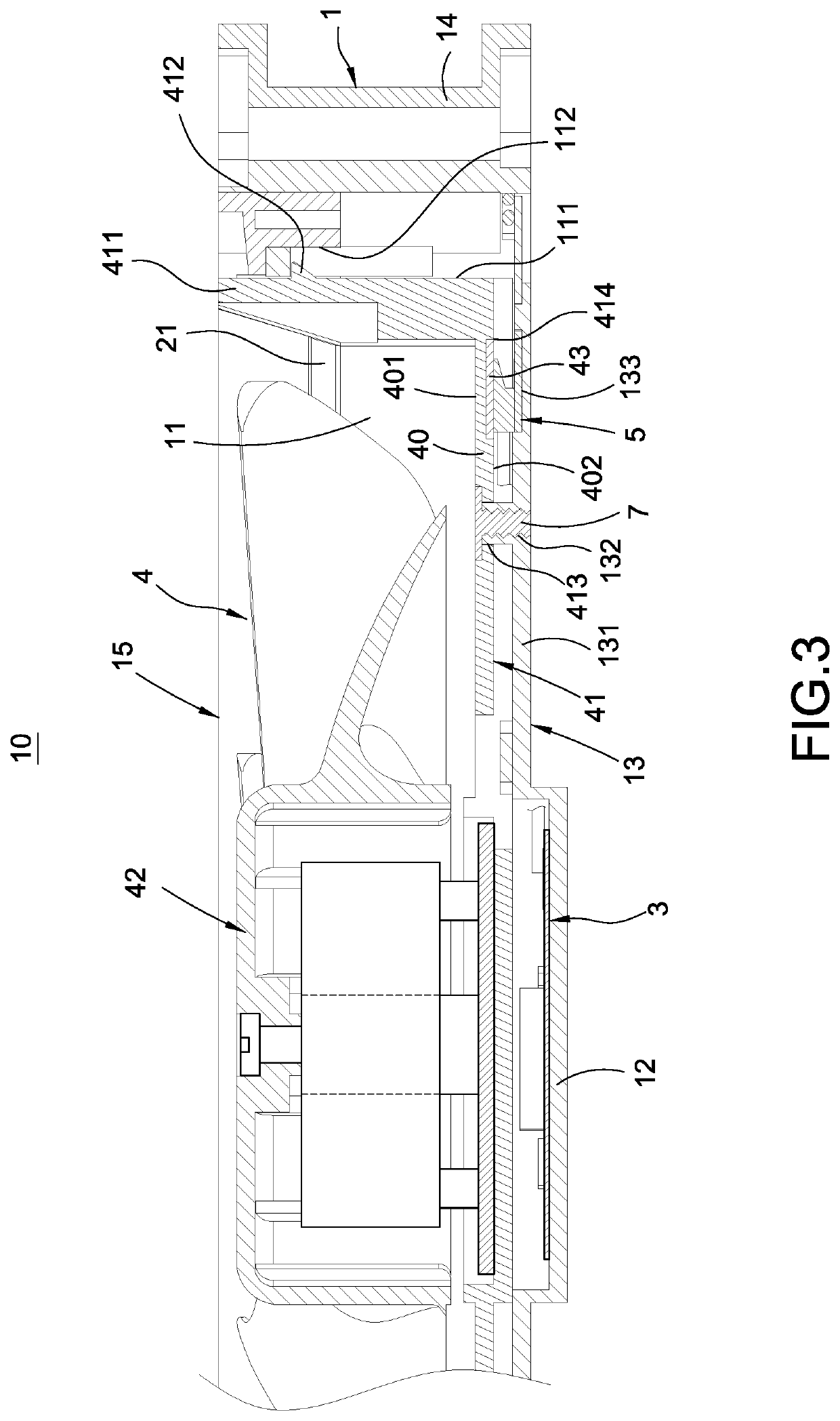
Embodiment Construction

[0012]The detailed description and technical details of the present invention will be explained below with reference to accompanying figures. However, the accompanying figures are only for reference and explanation, but not to limit the scope of the present invention.

[0013]Please refer to FIGS. 1-4. The present invention provides a cooling fan module. The cooling fan module 10 mainly comprises a fan frame 1, at least one light emitting part 2, an LED controller 3, a fan body 4, and an external connector 5.

[0014]As shown in FIGS. 1-4, the fan frame 1 has a ring wall 11. A plurality of slits 111 are disposed on the inner wall of the ring wall 11. A latching slot 112 is disposed on the bottom wall of each of the slits 111. In the current embodiment, the number of the slits 111 is two; the ring wall 11 is provided with two receiving slots 113 at two sides of the two slits 111.

[0015]Besides, the fan frame 1 further has a middle plate 12 and a plurality of supporting beams 13 which are in...


PUM


Abstract

A cooling fan module includes a fan frame, a light emitting part installed in the fan frame, an LED controller installed in the fan frame and electrically connected to the light emitting part, a fan body, and an external connector. The fan body includes a supporting stand detachably connected to the fan frame, a blade set installed on the supporting stand and can rotate with respect to the supporting stand, and a fan connector fixed to the supporting stand and electrically connected to the blade set. The external connector is fixed to the fan frame. The external connector can be electrically plugged in the fan connector to send a first signal; the external connector is electrically connected to the LED controller to send a second signal. Therefore, the cooling fan module has the advantages of easy assembly and reduced incorrect connection.

Description

BACKGROUND OF THE INVENTIONField of the Invention[0001]The present invention relates to a heat dissipation device, and in particular to a cooling fan module.Description of Related Art[0002]While the current computer becomes increasingly powerful, the heat generated by the computer host increases gradually. Thus, a cooling fan is required to be installed inside the computer to generate forced air flow to bring the heat out of the computer case. Also, the modern design tends to be novel so the cooling fan is equipped with the RGB LEDs showing red color, green color, and blue color such that the brilliant light effects can be produced during the operation of the cooling fan.[0003]However, to operate the cooling fan requires a power supply module and to provide the changing light effects for the red, blue and green light emitting diodes (RGB LEDs) also requires a signal module. Thus, the cooling fan has to be equipped with two connectors for external connection, which causes the complic...

Claims


Application Information

Patent Timeline
Patent Type & Authority Patents(United States)
IPC IPC(8): F04D29/00F21V33/00F21V23/00F04D29/52F04D19/00F21Y115/10
CPCF04D29/005F04D19/002F04D29/522F21V23/003F21V33/0096F21Y2115/10F04D25/0613F04D25/0693F04D29/646G06F1/20
Inventor LIN, CHUN-HUNGCHIEN, YI-SHEN
Owner TAIWAN MICROLOOPS CORP
Why Eureka
Try Eureka