Assembly for measuring the viscosity of fluids using microchannels

a technology of fluid viscosity and microchannel, which is applied in the direction of direct flow property measurement, indirect flow property measurement, instruments, etc., can solve the problems of large sums of samples, long collection time, and parts of the device that typically come in contact with the sample that need maintenance and can be expensive to replace, so as to improve the viscosity of the measuring assembly

Active Publication Date: 2021-02-23
UNIV OF CONNECTICUT
View PDF30 Cites 6 Cited by
  • Summary
  • Abstract
  • Description
  • Claims
  • Application Information

AI Technical Summary

Benefits of technology

[0006]The present disclosure provides improved viscosity measuring assemblies, and related methods of use. More particularly, the present disclosure provides advantageous measuring assemblies configured to measure the viscosity of samples / fluids (e.g., opaque or transparent liquids) using microchannels.

Problems solved by technology

In general, commercially available rheometers (e.g., viscometers for non-Newtonian fluids) require large sums of the sample, take a long time to gather measurements (e.g., hours) and can be expensive (e.g., $5000 or more) because they can be configured to meet a large variety of typically industrial applications.
The parts of the device that typically come in contact with the sample can require maintenance and can be expensive to replace (e.g., $200 or more).
As such, these rheometers are generally not currently used in health care.
Alternative solutions have been proposed, such as some microchannel or capillary based devices, however, in most cases these devices still require a long time to conduct the measurement due to manual signal processing, such as direct video processing, and are often as expensive as their counterparts.
Moreover, these devices can be expensive in time and money to fully manufacture, and may not be reasonably extended to a full consumer product.

Method used


Image

  • Assembly for measuring the viscosity of fluids using microchannels
  • Assembly for measuring the viscosity of fluids using microchannels
  • Assembly for measuring the viscosity of fluids using microchannels

Examples


example 1

[0046]In exemplary embodiments, the present disclosure provides a new and advantageous viscosity measuring assembly / method, as discussed further below.

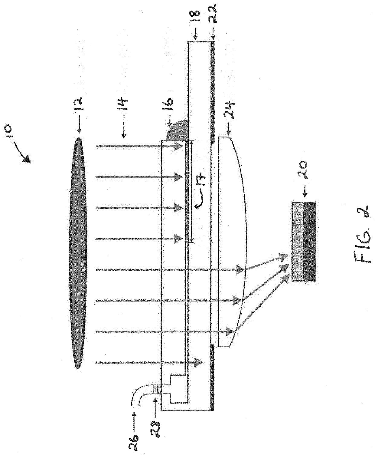
[0047]As shown in FIGS. 1-2, an exemplary measuring assembly 10 of the present disclosure can measure the viscosity of whole blood 16 and of other opaque fluids 16 (e.g., liquids). A small amount of the sample fluid 16 (e.g., about 20 μL) is sufficient, and the sample 16 can be deposited in contact with a microchannel opening of the substrate 18 (FIG. 2).

[0048]At the other end (e.g., opposite the fluid 16 entry), the microchannel of the substrate 18 may be exposed to atmospheric pressure through opening 26, which is in close proximity to valve / pressure sensor 28. As a result of atmospheric pressure exposure, the fluid 16 will traverse the microchannel due to capillary pressure. The fluid viscosity can be quantified by precisely measuring the length of the fluid column inside the microchannel and its velocity. This method produces visc...


PUM

PropertyMeasurementUnit
capillary pressureaaaaaaaaaa
viscosityaaaaaaaaaa
transparentaaaaaaaaaa

Abstract

The present disclosure provides improved viscosity measuring assemblies, and related methods of use. More particularly, the present disclosure provides advantageous measuring assemblies configured to measure the viscosity of samples / fluids (e.g., opaque or transparent liquids) using microchannels. The present disclosure provides for a viscosity measuring assembly (e.g., hand-held electronic measuring assembly) that is configured to measure the viscosity of samples / fluids (e.g., opaque or transparent Newtonian and non-Newtonian liquids, including blood, etc.), in a short period of time (e.g., within a couple of minutes) utilizing only about a droplet of fluid. The viscosity measuring assembly can include a substrate having a microchannel, a light source (e.g., a collimated low coherence light source), and a sensor (e.g., photodiode). The micro-channeled substrate may be disposable, and some of the other components may be reusable since they are substantially not directly exposed to the sample during operation of the viscosity measuring assembly.

Description

CROSS-REFERENCE TO RELATED APPLICATION[0001]The present application claims priority benefit to a provisional application entitled “Assembly for Measuring the Viscosity of Fluids Using Microchannels,” which was filed on May 4, 2017, and assigned Ser. No. 62 / 501,415. The entire content of the foregoing provisional patent application is incorporated herein by reference.FIELD OF THE DISCLOSURE[0002]The present disclosure relates generally to the field of viscosity measuring assemblies and, more particularly, to measuring assemblies configured to measure the viscosity of samples / fluids (e.g., opaque or transparent liquids) using microchannels.BACKGROUND OF THE DISCLOSURE[0003]In general, commercially available rheometers (e.g., viscometers for non-Newtonian fluids) require large sums of the sample, take a long time to gather measurements (e.g., hours) and can be expensive (e.g., $5000 or more) because they can be configured to meet a large variety of typically industrial applications. Th...

Claims


Application Information

Patent Timeline
Patent Type & Authority Patents(United States)
IPC IPC(8): G01N11/08G01N33/49G01N11/06G01N11/00
CPCG01N11/08G01N11/06G01N33/49G01N2011/008G01N2011/0026
Inventor LYKOTRAFITIS, GEORGEPARTOLA, KOSTYANTYN
Owner UNIV OF CONNECTICUT
Why Eureka
Try Eureka