System for displaying and controlling medical monitoring data

a medical monitoring and data display technology, applied in the field of patient monitoring devices, can solve problems such as chaos, device disarray, and potentially chaotic experience, and achieve the effects of reducing patient pain, reducing patient pain, and reducing patient comfor

Active Publication Date: 2021-03-02
MASIMO CORP
View PDF1194 Cites 216 Cited by
  • Summary
  • Abstract
  • Description
  • Claims
  • Application Information

AI Technical Summary

Problems solved by technology

Sometimes, the disparity in devices leads to a need to simply print and store paper from each device in a patient's file for caregiver review.
The result of such device disparity is often a caregiver environment scattered with multiple displays and alarms leading to a potentially chaotic experience.
Such chaos can be detrimental to the patient in many situations including surgical environments where caregiver distraction is unwanted, and including recovery or monitoring environments where patient distraction or disturbance may be unwanted.
However, as medical device technology expands, such multi-monitor devices begin to be obsolete the moment they are installed.

Method used


Image

  • System for displaying and controlling medical monitoring data
  • System for displaying and controlling medical monitoring data
  • System for displaying and controlling medical monitoring data

Examples


example hub embodiments

II. Example Hub Embodiments

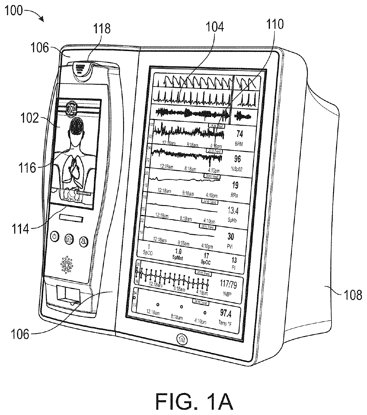
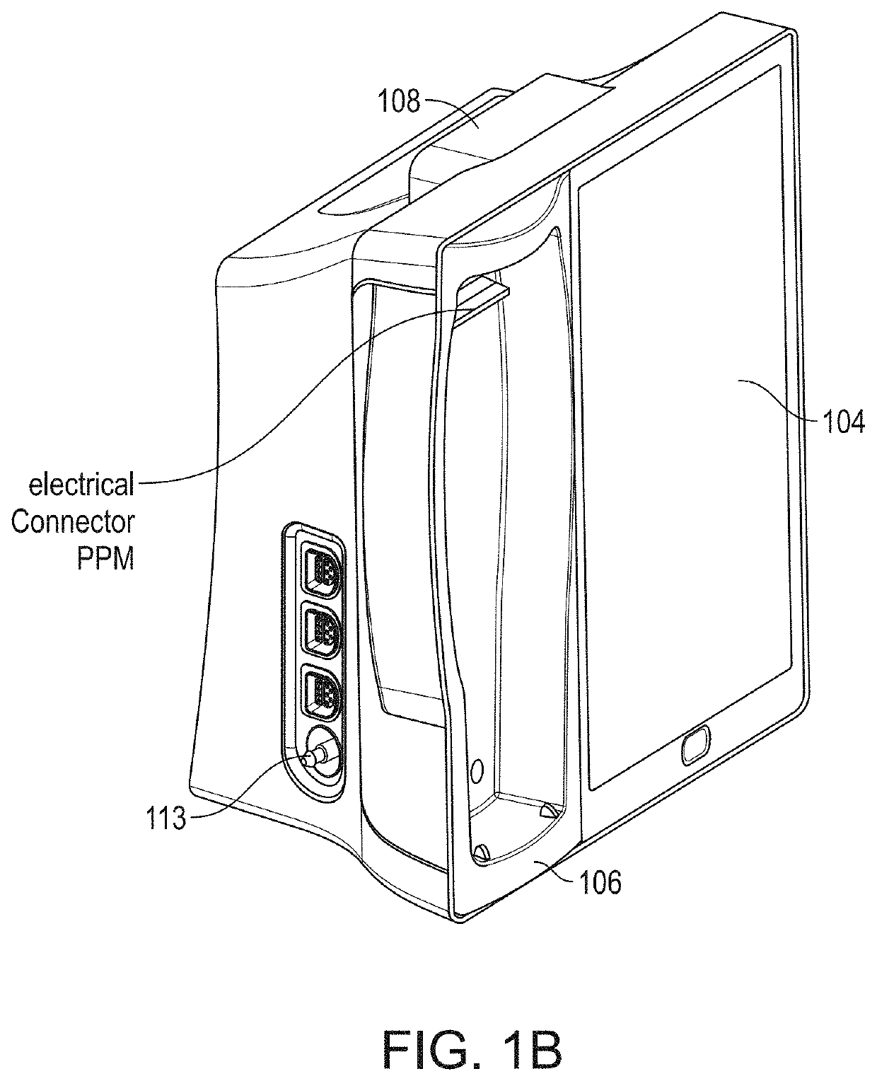
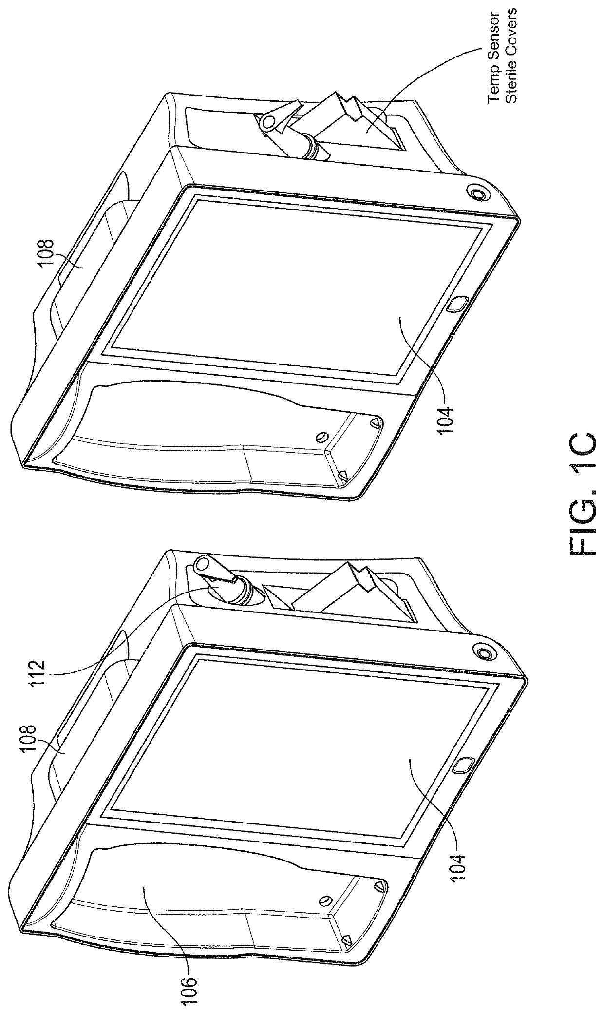
[0091]FIG. 1A illustrates a monitoring environment including a perspective view of an exemplary medical monitoring hub 100 with an exemplary docked portable patient monitor (PPM) 102 according to an embodiment of the disclosure. The hub 100 includes a display 104, and a docking station 106, which in an embodiment is configured to mechanically and electrically mate with the portable patient monitor 102, each housed in a movable, mountable and portable housing 108. The housing 108 includes a generally upright inclined shape configured to rest on a horizontal flat surface, although the housing 108 can be affixed in a wide variety of positions and mountings and comprise a wide variety of shapes and sizes.

[0092]In an embodiment, the display 104 may present a wide variety of measurement and / or treatment data in numerical, graphical, waveform, or other display indicia 110. In an embodiment, the display 104 occupies much of a front face of the housing 108, althoug...


PUM


Abstract

A first medical device can acquire a physiological parameter value from a patient and communicate the physiological parameter value to a medical network interface. The medical network interface can link a patient ID associated with the physiological parameter and a device ID associated with the first medical device with the medical network interface's device ID. The medical network interface can pass the physiological parameter value to a second medical device for further processing or routing to another medical device.

Description

RELATED APPLICATIONS[0001]This application is related to the following U.S. patent applications, the disclosures of which are incorporated in their entirety by reference herein:[0002]App. No.Filing DateTitle62 / 463,452Feb. 24, 2017PATIENT MONITORCOMMUNICATION PLATFORM62 / 463,297Feb. 24, 2017MODULAR MULTI-PARAMETERPATIENT MONITORING DEVICE62 / 463,517Feb. 24, 2017SYSTEM FOR DISPLAYING ANDCONTROLLING MEDICALMONITORING DATA62 / 503,109May 8, 2017SYSTEM FOR DISPLAYING ANDCONTROLLING MEDICALMONITORING DATA62 / 535,757Jul. 21, 2017SYSTEM FOR DISPLAYING ANDCONTROLLING MEDICALMONITORING DATA62 / 463,614Feb. 25, 2017PATIENT MONITORCOMMUNICATION PLATFORM[0003]Many of the embodiments described herein are compatible with embodiments described in the above related applications. Moreover, some or all of the features described herein can be used or otherwise combined with many of the features described in the applications listed above.FIELD OF THE DISCLOSURE[0004]The present disclosure relates generally to ...

Claims


Application Information

Patent Timeline
Patent Type & Authority Patents(United States)
IPC IPC(8): A61B5/1455G16H10/60G06F13/42G06F13/40G06F13/38G16H40/40G16H40/63G16H40/67
CPCA61B5/14552G06F13/385G06F13/4004G06F13/4282G16H10/60G16H40/40G16H40/63G16H40/67
Inventor MUHSIN, BILALBARKER, NICHOLAS EVAN
Owner MASIMO CORP
Why Eureka
Try Eureka