Internal combustion cleaning

a technology of internal combustion and cleaning equipment, applied in the direction of machines/engines, chemistry apparatuses and processes, engine components, etc., can solve the problems of increasing the compression ratio, notoriously harmful, and subsequent increase in pollutant emissions

Active Publication Date: 2021-03-02
GE JENBACHER
View PDF10 Cites 0 Cited by
  • Summary
  • Abstract
  • Description
  • Claims
  • Application Information

AI Technical Summary

Benefits of technology

[0008]It is the object of the invention to provide an easier and / or faster way to clean such a combustion chamber, wherein it is possible to reduce the costs for maintenance work.
[0011]With the help of such a scraping tool according to the invention a cavity (as for example by a combustion chamber), which is only accessible by a small opening, can be cleaned without very time-consuming dismantling of attachment parts in order to allow a good accessibility. With the help of a scraping tool according to the invention, the at least one scraping unit can be introduced in a first position, can be swiveled into a second position and can clean the cavity in this second position.
[0016]In a preferred embodiment of the invention a bore can provided inside the scraper tool to remove a combustion residue from the cavity. It can be provided that a conduct is provided, connected this bore, which can be used to remove the combustion residue from the cavity, with a suction apparatus. With the help of such a preferred embodiment of the invention, an easy and fast possibility is provided to remove the combustion residue from the cavity.
[0024]It can be provided that with the help of the at least one scraper unit a cylinder head inside the combustion chamber and / or a wall of the combustion chamber and / or a upper surface of the piston can be cleaned.
[0025]It can also be provided that after cleaning a piston is moved away from the cylinder head before a combustion residue, produced by the cleaning process, is removed. This moving away of the cylinder from the cylinder head minimize the risk any debris remaining trapped between the piston ring and the cylinder wall.

Problems solved by technology

One of the most extended servicing challenges that appear in industrial reciprocating engine applications is the gradual buildup of carbon deposits on the walls of the combustion chamber.
The carbon deposits originate mainly from the incomplete combustion of the fuel, which are primarily driven by a combination of insufficient mixing of the fuel and oxidants and the impurities present in the fuel.
Impurities in the fuel can originate from a lack of fuel refinement, a contamination during transport, or both.
Thus, the products of combustion tend to include different types of carbon particles, which are notoriously harmful due to the ease with which they adhere to surfaces and the difficulty to remove them.
The buildup of these deposits has a downstream effect in the engine performance by bringing an unwanted increase in the compression ratio, the appearance of hot spots—which often lead to engine knocking—and the subsequent increase in pollutant emissions.
The introduction of fuel additives, however, is less than ideal in the industrial environment, where the cost of the fuel has a major impact on the cost of products.
Although the system seems effective for the outer piston, it doesn't target the deposits on the cylinder head, cylinder liner nor the central part of the piston crown.

Method used


Image

  • Internal combustion cleaning
  • Internal combustion cleaning

Examples


Embodiment Construction

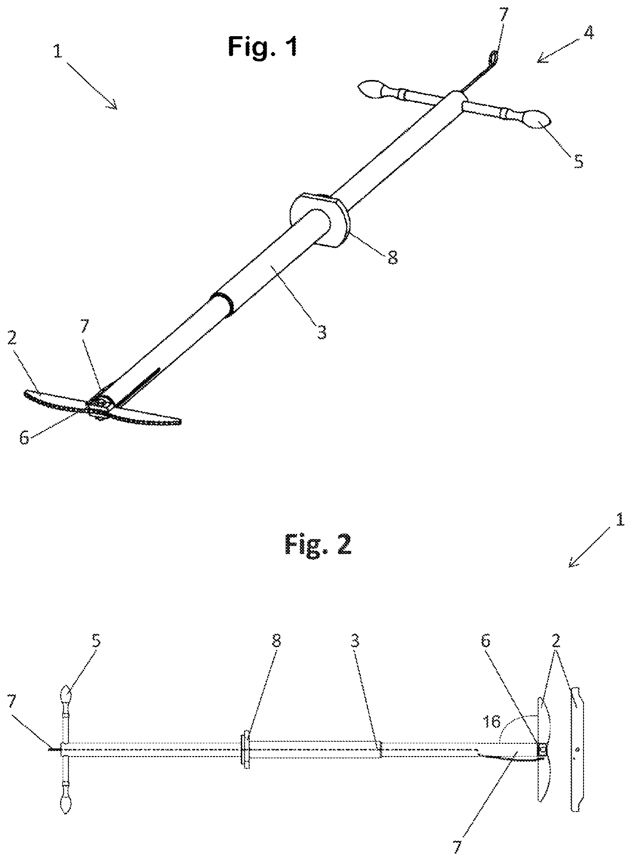
[0032]FIG. 1 shows an isometric view of a scraping tool 1 according to an embodiment of the invention. The scraping tool 1 comprises a longitudinal carrier 3, which can be provided (as shown in this figure) with a telescopic portion for varying the length of the longitudinal carrier 3. Further the longitudinal carrier 3 comprises a stop 8, which will be described in more detail in FIG. 3. A scraper unit 2 is swivel mounted on the longitudinal carrier 3 with the help of a bolt 6. A swivel motion of the scraper unit 3 can be induced by the wire 7. The wire 7 is fixed to the scraper unit 2. A rotational or longitudinal motion of the scraper unit 2 can be achieved by moving the handle 5, which takes the function of the activation device 4, in an appropriate way.

[0033]In FIG. 2 a side view of FIG. 1 can be seen. In this view it can be seen that the wire 7 is mounted eccentrically on the scraping unit 2. The wire 7 is leading through the longitudinal carrier 3 to an activation device 4. B...


PUM


Abstract

A scraping tool for cleaning a combustion chamber of an internal combustion engine is provided. The scraping tool includes at least one scraper unit, a longitudinal carrier, and an activation device. The at least one scraper unit is configured to clean at least one surface of a cavity. The longitudinal carrier, preferably a rod or a tube, connects the at least one scraper unit with the activation device. The at least one scraper unit is swivel mounted on the longitudinal carrier and can be swiveled from a first position for introducing the at least one scraper unit into the cavity to a second position for cleaning at least one surface of the cavity. In the first position, the at least one scraper unit is disposed substantially parallel to the longitudinal carrier. In the second position, the at least one scraper unit is disposed at an angle between 70° and 110°, preferably between 80° and 100°, and more preferably at substantially 90°, with respect to the longitudinal carrier.

Description

BACKGROUND OF THE INVENTION[0001]This invention relates to a scraping tool for cleaning a combustion chamber of an internal combustion engine with the features of the preamble of claim 1 and a method for cleaning a combustion chamber of an internal combustion engine.BRIEF DESCRIPTION OF THE INVENTION[0002]One of the most extended servicing challenges that appear in industrial reciprocating engine applications is the gradual buildup of carbon deposits on the walls of the combustion chamber. The carbon deposits originate mainly from the incomplete combustion of the fuel, which are primarily driven by a combination of insufficient mixing of the fuel and oxidants and the impurities present in the fuel. Impurities in the fuel can originate from a lack of fuel refinement, a contamination during transport, or both. Thus, the products of combustion tend to include different types of carbon particles, which are notoriously harmful due to the ease with which they adhere to surfaces and the di...

Claims


Application Information

Patent Timeline
Patent Type & Authority Patents(United States)
IPC IPC(8): F02B77/04B08B1/00
CPCF02B77/04B08B1/005
Inventor DOMINIAK, KRZYSZTOF ANDRZEJHOTTER, PATRICKSEKRECKI, MICHAL LUKASZWEIDL, REBECCA
Owner GE JENBACHER
Why Eureka
Try Eureka