Cooling system, motor vehicle and method for cooling same

a technology for cooling systems and motor vehicles, applied in the field of cooling systems, can solve the problems of limited capacity of fans and severe blockage of air in the direction of fans, and achieve the effects of reducing the electrical supply of vehicles

Active Publication Date: 2021-03-09
DR ING H C F PORSCHE AG
View PDF17 Cites 0 Cited by
  • Summary
  • Abstract
  • Description
  • Claims
  • Application Information

AI Technical Summary

Benefits of technology

[0009]The invention relates to efficient cooling air management that includes switching off an individual cooler or radiator that is not required, thereby saving energy and relieving the electrical supply of the vehicle of load. By focusing the air flow from the central fan, significantly more air can be provided per cooler than with the conventional individual fan system. Thus, the quantity of air flowing through a cooler is not absolutely dependent on the driving speed of the vehicle, but rather can be controlled in a targeted manner by valves. The central fan has a geometrical flexibility that overcomes the prior art problem of severe blockage of the cooling air in the direction of the engine compartment. Additionally, the geometrical flexibility permits a fan size that is entirely independent of the package in the region of the cooler and enables the constructor to adapt the capacity of the fan in a targeted manner to the requirements of the application by suitable dimensioning.
[0010]Cooling air openings are arranged fluidically in the air system between the valves, and the coolers for supplying the cooling air to the respective cooler can be provided with an annular gap that encircles each cooling air opening for accelerating the cooling air supplied to the respective cooler. The fans mounted upstream of the individual coolers according to the conventional approach are replaced by the annular gap mentioned, which leads to a considerable saving on weight.
[0011]The annular gap may have a cross section that tapers fluidically in the direction of the air guide for sucking up the cooling air via the cooling air opening. The annular gap with a cross section that becomes narrower accelerates the cooling air from the central air system particularly efficiently, and produces a negative pressure that generates suction that sucks up further cooling air via the cooling air opening.

Problems solved by technology

The geometry of the fan results in severe blockage of the air in the direction of the engine compartment.
Furthermore, the fan is limited in capacity by the size thereof.

Method used


Image

  • Cooling system, motor vehicle and method for cooling same
  • Cooling system, motor vehicle and method for cooling same

Examples


Embodiment Construction

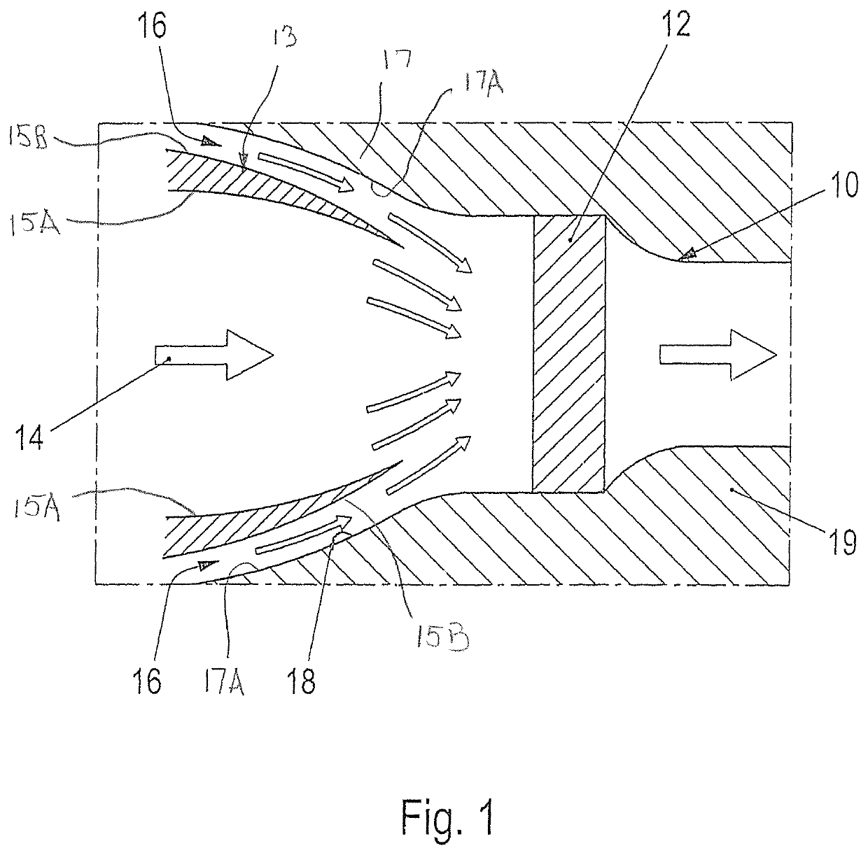
[0016]FIG. 1 illustrates, with reference to a partial section, the structural design of a cooling system 10 according to an embodiment of the invention. The cooling system 10 has four coolers or radiators for cooling the vehicle. FIG. 1 reproduces by way of example the detail of one of the coolers 12.

[0017]FIG. 1 shows a cooling air opening 14 that is mounted fluidically upstream of the cooler 12 for supplying the cooling air 16 to the cooler 12. More particularly, an annular wall 13 is disposed upstream of the cooler 12 and has an inner circumferential surface 15A that defines the cooling air opening 14. The inner circumferential surface 15A of the annular wall 13 tapers to smaller radial dimensions in a downstream direction. An encircling wall 17 is spaced out from the annular wall 13 and defines an annular gap 18 between an outer circumferential surface 15B of the annual wall 13 and an inner circumferential surface 17A of the encircling wall 17. The cross-sectional area of the an...


PUM


Abstract

A cooling system (10) for a motor vehicle has an air system that fluidically connects a plurality of coolers (12) for supplying the coolers (12) with cooling air (16). An air fan is arranged fluidically in the air system for conveying the cooling air (16) to the coolers (12). Valves are arranged fluidically in the air system upstream of the coolers (12), for blocking the cooling air (16) conveyed to the respective cooler (12).

Description

CROSS REFERENCE TO RELATED APPLICATION[0001]This application claims priority under 35 USC 119 to German Patent Appl. No. 10 2014 112 609.2 filed on Sep. 2, 2014, the entire disclosure of which is incorporated herein by reference.BACKGROUND1. Field of the Invention[0002]The present invention relates to a cooling system for a motor vehicle. The invention further relates to a method for using a cooling system of this type, to a corresponding computer program and to a machine-readable storage medium with such a program.2. Description of the Related Art[0003]Systems for supplying coolers or radiators in a motor vehicle with cooling air are known in vehicle engineering. These systems direct a flow of cooling liquid through a cooler and cool the cooling liquid by cooling air flowing there through. Thus, the cooling liquid can be supplied again to a cooling system. A fan customarily is located upstream of the cooler for sucking up the air so that a constant quantity of air—substantially cor...

Claims


Application Information

Patent Timeline
Patent Type & Authority Patents(United States)
IPC IPC(8): B60H1/00F01P11/10F01P7/10F24F1/01
CPCF01P11/10B60H1/00828B60H1/00842F01P7/10F24F1/01B60H2001/00121B60H1/00764B60H1/00
Inventor PEHNERT, BJOERNWARBECK, THOMASKUHN, DAVID
Owner DR ING H C F PORSCHE AG
Why Eureka
Try Eureka