
Air bag assembly with pumping function

a technology of air bags and components, applied in the direction of pump components, positive displacement liquid engines, fastenings, etc., can solve the problems of bulky air suction devices, inconvenient assembly on other objects, and the defects of the above-mentioned retractable parts, so as to facilitate the recovery of internal pressure

Active Publication Date: 2020-06-25
UNIVERSAL TRIM SUPPLY CO LTD
View PDF0 Cites 0 Cited by
  • Summary
  • Abstract
  • Description
  • Claims
  • Application Information

AI Technical Summary

Benefits of technology

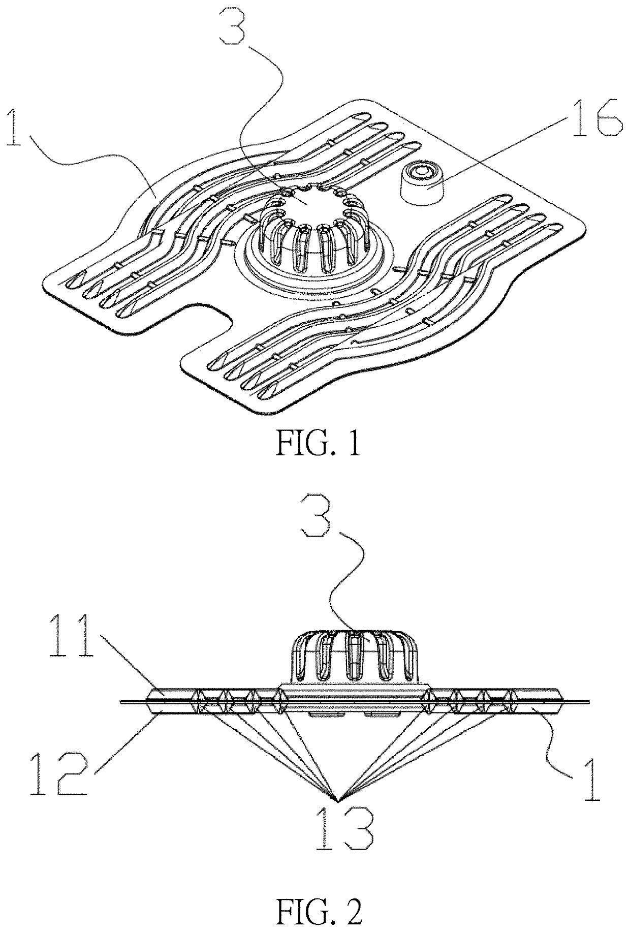
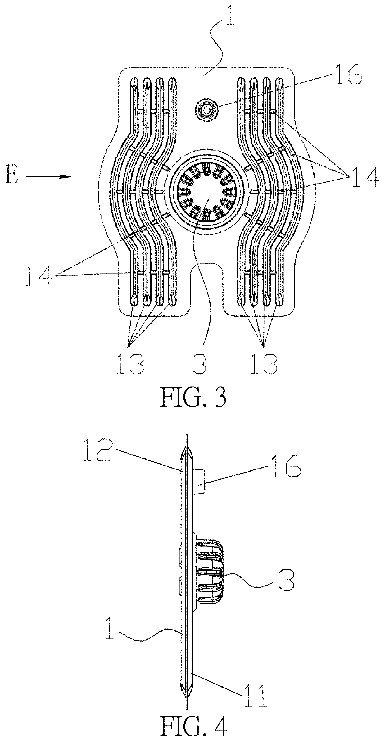
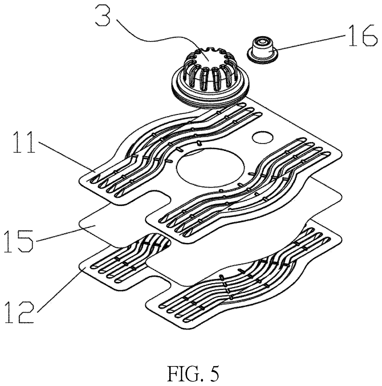
The present invention is an air bag assembly that has the advantages of being simple to operate, small in size, and easy to install on other objects. The assembly includes a rotary cover that can be rotated to pump the air bag. The assembly also has a second check valve to control air flow and ensure the vacuum suction force of the pump body is ensured for faster pumping. The assembly further includes a gauze layer to facilitate air flow and a venting valve for recovery of the air bag's internal pressure. Overall, the air bag assembly is convenient, compact, and efficient.

Problems solved by technology

However, it needs large action of operation during the pumping process, which requires sufficient space, and the pumping cylinder makes the air suction device bulky.
Therefore, the existing manual air suction device is only suitable for use alone, and it is inconvenient to be assembled on other objects.
However, the above-mentioned retractable parts mainly have following defects.
The shoelace or the rope needs to be knotted to tighten the object, the knot is easy to loosen, and the knot needs to be repeated after loosening, so the operation is complicated and inconvenient.
The elastic band and the elastic stretching fabric can be stretched and contracted and are convenient to use, but it is prone to elastic fatigue after a long time of use and loses elasticity.

Method used


Image

  • Air bag assembly with pumping function
  • Air bag assembly with pumping function
  • Air bag assembly with pumping function

Examples


first embodiment

[0035]The operational process of the air bag assembly according to the present invention is introduced as follows. First, the rotary cover 3 is rotated to make the convex part of the rotary cover 3 press the convex portion 202 of the pump body 20 so as to deform the pump body 20. Therefore, air inside the pump body 20 is compressed to increase the pressure, the second check valve 5 opens the second air hole 21, and the air inside the pump body 20 enters into the interior of the rotary cover 3 through the second air hole 21 and is discharged to the outside atmosphere through the air outlet 30. At this time, the first check valve 4 closes the first air hole 10.

[0036]Secondly, the rotating cover 3 is rotated to make the convex part of the rotary cover 3 embed in the concave portion 201 of the pump body 20 and make the convex portion 202 of the pump body 20 embed in the concave part of the rotary cover 3, so that the deformed pump body can be resiliently recovered, a shape of the pump b...

second embodiment

[0054]The operational process of the air bag assembly according to the present invention is introduced as follows. First, the rotary cover 3 is rotated to make the convex part of the rotary cover 3 press the convex portion 202 of the pump body 20 so as to deform the pump body 20. Therefore, the air inside the pump body 20 is compressed to increase the pressure, and the air inside the pump body 20 enters into the interior of the rotary cover 3 through the second air hole 21 and is discharged to the outside atmosphere through the air outlet 30. At this time, the first check valve 4 closes the first air hole 10.

[0055]Secondly, the rotating cover 3 is rotated to make the convex part of the rotary cover 3 embed in the concave portion 201 of the pump body 20 and make the convex portion 202 of the pump body 20 embed in the concave part of the rotary cover 3, so that the deformed pump body can be resiliently recovered, the shape of the pump body 20 is restored, and the internal volume of th...


PUM


Abstract

An air bag assembly includes an air bag having a first hole, a suction pump, a rotary cover and a first check valve. A pump body of the suction pump is deformable and provided with a second air hole. The rotary cover includes an air outlet communicating with the second air hole. A convex part and a concave part of the rotary cover are configured to engage with a concave portion and a convex portion of the pump body, respectively. The first check valve allows air to enter into the interior of the pump body from the interior of the air bag through the first air hole. The air bag can be pumped by rotating the rotary cover. The air bag assembly has advantages of simple operation, small volume and low requirement on operating space, and capable of being assembled on other objects, which is convenient to use and carry.

Description

BACKGROUND OF THE INVENTION1. Field of the Invention[0001]The present invention relates to an air bag assembly, and more particularly, to an air bag assembly with advantages of simple operation, small volume and low requirement on operating space, and capable of being assembled on other objects, which is convenient to use and carry.2. Description of the Prior Art[0002]In an existing manual air suction device, a bag body is often pumped by pulling a piston in an air cylinder, such as vacuuming a clothes storage bag by the air cylinder. However, it needs large action of operation during the pumping process, which requires sufficient space, and the pumping cylinder makes the air suction device bulky. Therefore, the existing manual air suction device is only suitable for use alone, and it is inconvenient to be assembled on other objects. At present, there is no air suction product on the market, which is small in size, has low requirement on operating space, and is convenient to be asse...

Claims


Application Information

Patent Timeline
IPC IPC(8): F04B37/14F04B39/00
CPCF04B39/00F04B37/14A43C11/00F04B33/00F04B39/10F04B39/14F04B45/00
Inventor YANG, SHIH-SHENG
Owner UNIVERSAL TRIM SUPPLY CO LTD
Learn More