
Part load performance improvement using deformable bore plugs

Inactive Publication Date: 2014-04-24
GENERAL ELECTRIC CO
View PDF5 Cites 13 Cited by
  • Summary
  • Abstract
  • Description
  • Claims
  • Application Information

AI Technical Summary

Benefits of technology

The patent describes a method to control the air pressure in gas turbines to reduce emissions and improve efficiency. By reducing airflow through certain channels, the air pressure across certain parts of the machine is changed. This change helps to reduce air leaks and manage harmful emissions like CO and NOx. The method also allows more air to support combustion during certain parts of the operation. Overall, this method helps to manage emissions and control the performance of gas turbines.

Problems solved by technology

The high energy combustion gases create a harsh environment, causing oxidation, erosion and corrosion of downstream hardware.
If the anticipated cooling flow is incorrect, then cooling either will be inadequate, causing the temperatures in the 1FWSP to be too high, which can result in shortened life expectancy of the components being cooled, or will be excessive, resulting in the unnecessary diversion of compressor air that can result in operational inefficiency.
Of course, because the boreplugs are opened or removed on installation based on anticipated cooling flow, correction of the cooling flow by addition or removal of plugs must await maintenance, as removal of a gas turbine from service to accomplish this modification is not cost effective.
Below this load, carbon monoxide (CO) emissions can increase exponentially and cause the system as a whole to go out of emissions compliance.
If a gas turbine has to be shutdown because it cannot remain in emissions compliance due to a low power demand, the other equipment in a combined cycle application also may need to be taken offline.
Bringing these other systems online again after a gas turbine shutdown may be expensive and time consuming.
Such startup requirements may prevent a power plant from being available to produce power when the demand is high.
Current gas turbine design have several limitation on minimum allowable air flow to the combustor below a predetermined gas turbine load which impacts the fuel air ratio also the combustion temperature and increases the emission at lower gas turbine load.
And while one well-known SMA, nitinol, or NiTi having roughly an equal atomic percentage of Ni and Ti, is unsuitable for use as a boreplug opening due to the high temperatures experienced in the operation in a gas turbine engine, other SMAs having the ability to survive high temperatures of operation as well as the corrosive, oxidative environment of a gas turbine engine may be suitable.

Method used

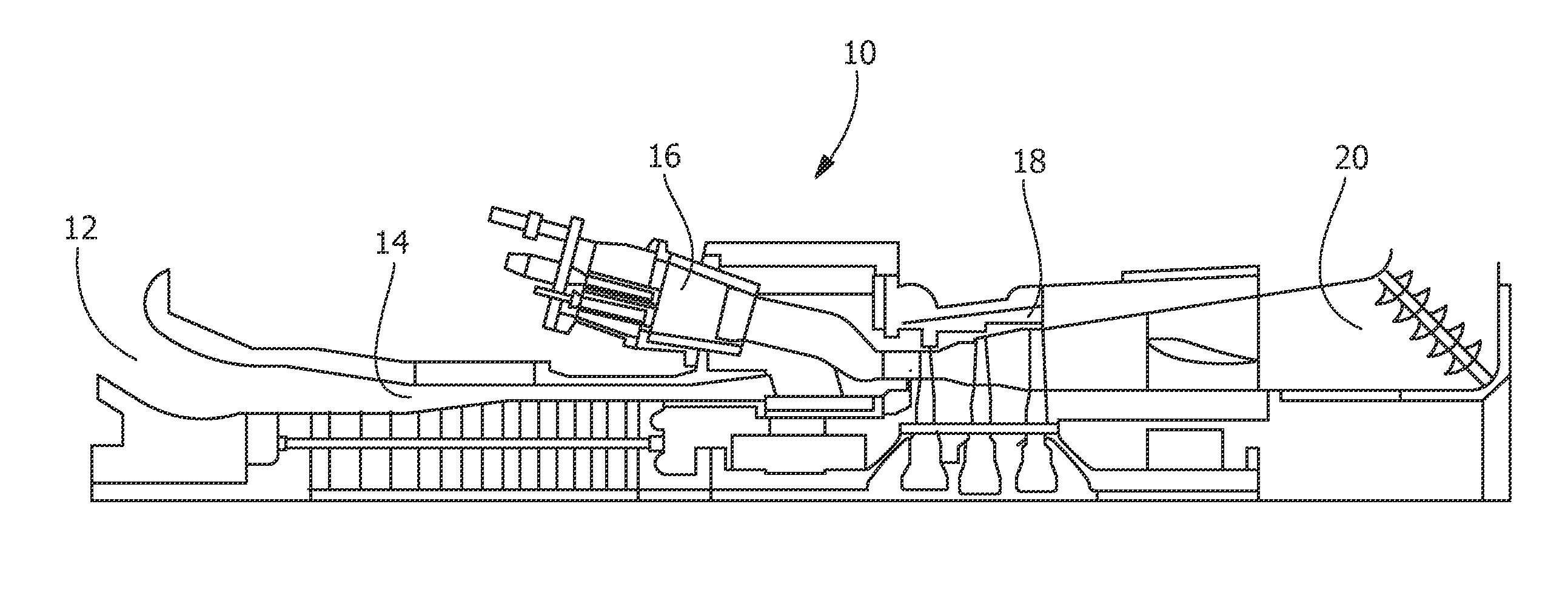
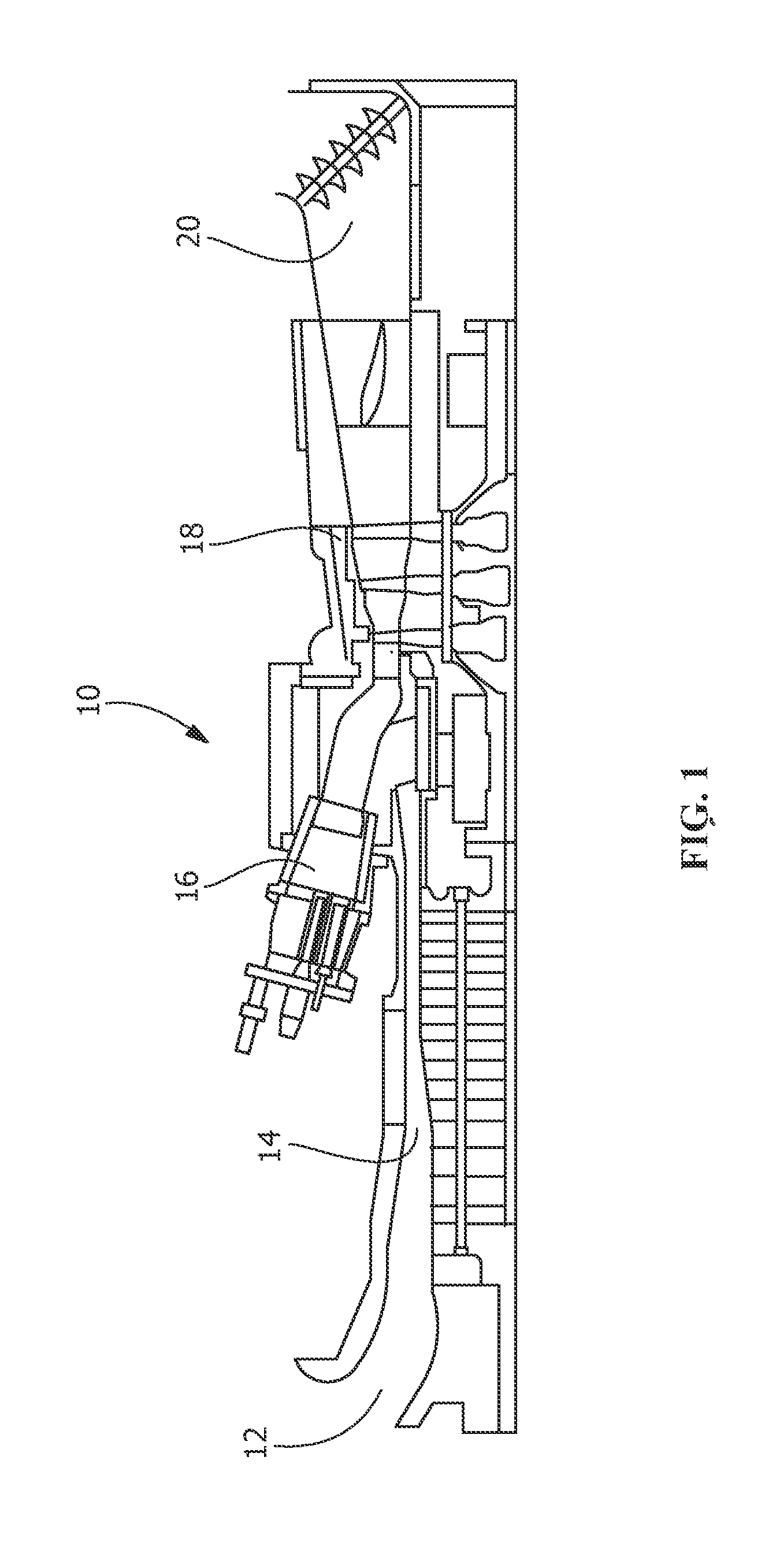
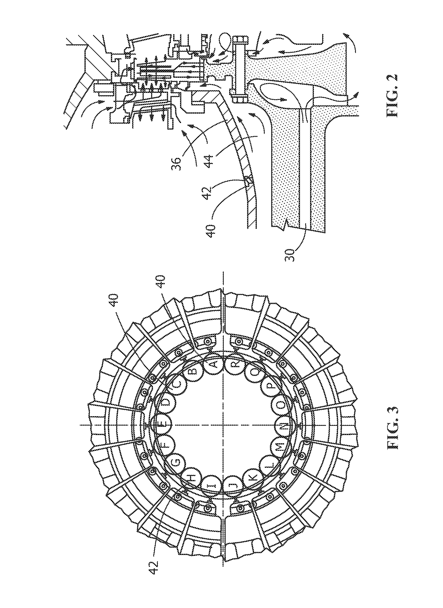

Image

  • Part load performance improvement using deformable bore plugs
  • Part load performance improvement using deformable bore plugs
  • Part load performance improvement using deformable bore plugs

Examples


Embodiment Construction

[0018]The present invention utilizes the unique properties of SMAs to provide cooling based on temperature. SMAs are characterized by temperature-dependent phase changes, the phases generally being a low temperature martensitic phase and an elevated austenitic phase. While SMAs can exhibit one-way shape memory, two way shape memory of SMAs makes cooling modulation possible. Two way shape memory is characterized by a shape transition both upon heating from the martensitic phase to the austenitic phase, as well as upon cooling from the austenitic phase to the martensitic phase. Two way shape memory may be either extrinsic or intrinsic. Intrinsic behavior is induced in SMAs through processing, which includes deformation of the SMA material while in the martensitic phase, followed by multiple heating and cooling cycles through the transformation temperature range under constraint. Once processing is complete, shape changes between the low temperature state and the high temperature state...


PUM

PropertyMeasurementUnit
Temperatureaaaaaaaaaa
Flow rateaaaaaaaaaa
Shape memory effectaaaaaaaaaa

Abstract

A cooling arrangement for a gas turbine engine. The cooling arrangement comprises a discharge channel for air flow from a compressor, a first cooling channel and at least one aperture providing communication between the flow of air through the discharge channel and the first cooling channel. A restrictor device in the aperture regulates the flow of air between the discharge channel and the first cooling channel. The restrictor device deforms to vary air flowing through the aperture in response to a physical condition of the engine. This physical condition of the engine may be that of the temperature of air flowing through the discharge channel, the restrictor device responding to regulate the flow of air based on that temperature. The restrictor device may be a two-way shape memory alloy.

Description

FIELD OF THE INVENTION[0001]The present invention is directed generally to the use of shape memory alloys in gas turbine engine components, and specifically to the use of shape memory alloys to control cooling of turbine engine components with changing temperature.BACKGROUND OF THE INVENTION[0002]Gas turbine engines operate by burning fuel and extracting energy from the combusted fuel to generate power. Atmospheric air is drawn into the engine from the environment, where it is compressed in multiple stages to significantly higher pressure and higher temperature. A portion of the compressed air is then mixed with fuel and ignited in the combustor to produce high energy combustion gases. The high energy combustion gases then flow through the turbine section of the engine, which includes a plurality of turbine stages, each stage comprising turbine vanes and turbine blades mounted on a rotor. The high energy combustion gases create a harsh environment, causing oxidation, erosion and cor...

Claims


Application Information

Patent Timeline
IPC IPC(8): F02C7/12
CPCF02C7/12F01D5/082F05D2300/505F01D25/12F01D17/105F05D2300/502F05D2220/32F02C9/18F02C6/08F01D25/08F01D25/14F01D5/08F01D17/10F02C3/04F02C7/141F02C7/18F04D29/522F04D29/582F05D2240/35F05D2260/20F05D2300/173F05D2300/504
Inventor GIRI, SHEO NARAINJHA, SANJEEV KUMARPEMMI, BHASKARBOOMANAKATTE, HARISHDONKADA, SANTHOSHGUMPINA, KRISHNA KISHOREMAZUMDER, INDRAJITSAHA, RAJARSHI
Owner GENERAL ELECTRIC CO
Learn More