Air circulation control device

a technology of air circulation and control device, which is applied in the direction of instruments, heating types, static/dynamic balance measurement, etc., can solve the problem of insufficient energy to power the fan

Inactive Publication Date: 2006-07-06
DUNSTAN JAMES EDWARD +1
View PDF6 Cites 20 Cited by
  • Summary
  • Abstract
  • Description
  • Claims
  • Application Information

AI Technical Summary

Benefits of technology

[0020] In a further embodiment, the system may be tied into a weather predicting system to plan ahead for the collection and use of electrical energy over a period of days. For example, if today is predicted to be warm and sunny, but not too hot, but the next three days are predicted to be overcast but also warm, the system can store excess energy today for use in the next few days, even if the result is that today the temperature is allowed to drift higher than optimally desired by a user. The CCS can make the determination that a slight temperature increase today is better than very large temperature increases over the next few days. An additional aspect of this embodiment may be the ability of a user to communicate and “fine tune” the CCS for personal needs such as placing the system in “conserve” mode during days when the user is away.

Problems solved by technology

Finally, there may be instances in which it is slightly overcast, the collection device is producing energy, but that energy is insufficient to power the fan (e.g. below the minimum input voltage of the system).

Method used


Image

  • Air circulation control device
  • Air circulation control device
  • Air circulation control device

Examples


Embodiment Construction

[0026] The following detailed description of the invention refers to the accompanying drawings. The same reference numbers in different drawings identify the same or similar elements. Also, the following detailed description does not limit the invention.

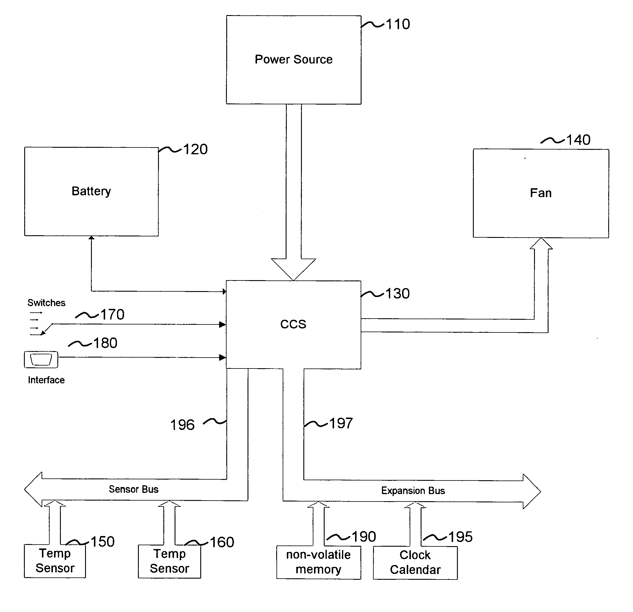
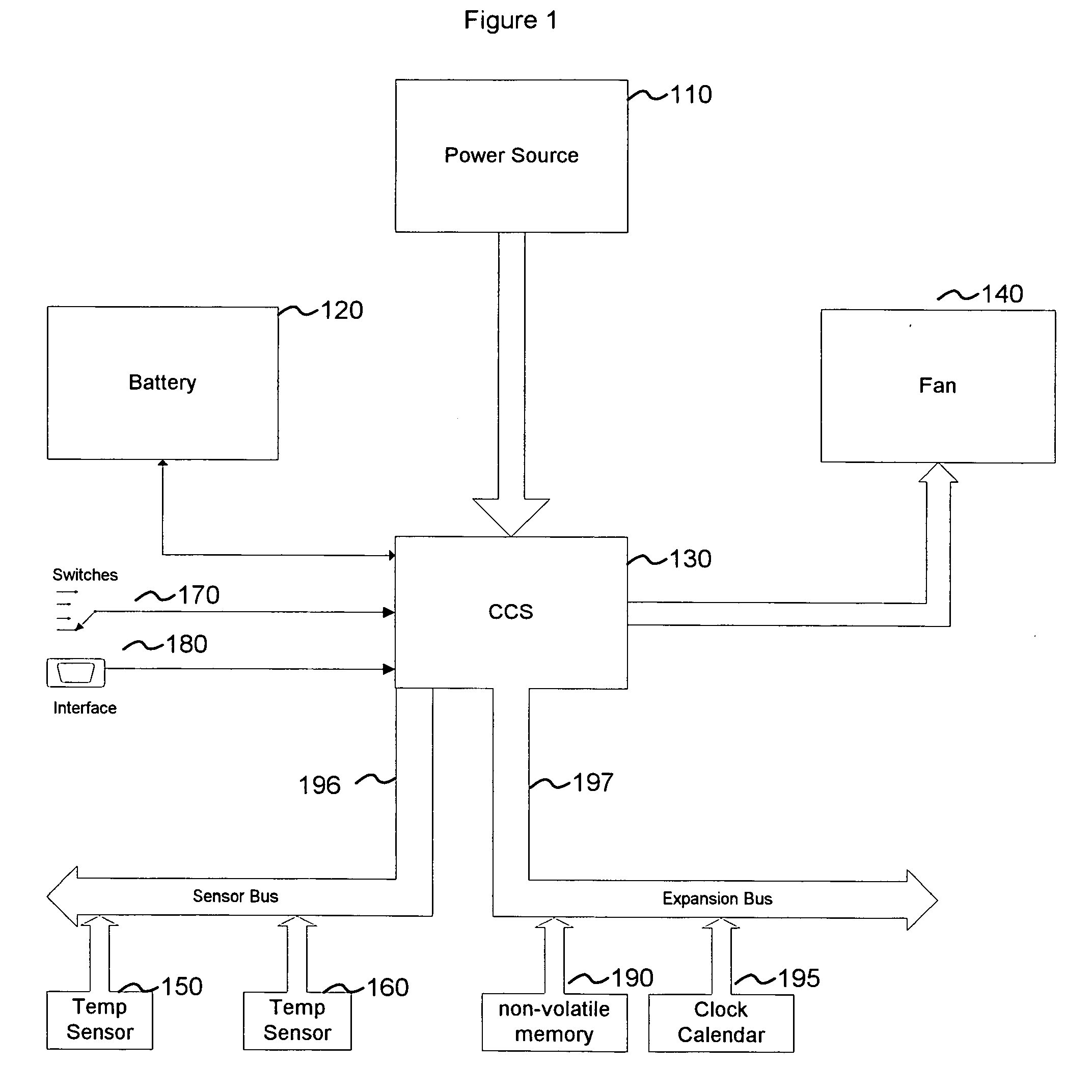
[0027]FIG. 1 is a block diagram of the basic configuration of the system. The current invention includes a power delivery device, such as a solar collector (110), battery (120), temperature sensors (150 and 160), computational control system (CCS)

[0028] (130) and fan system (140). The power delivery device (110) sends electrical power to the system. The electricity produced by the solar collector device (110) charges the battery (120). The CCS (130) performs one or more of the following functions: [0029] a) Monitors the temperature of the enclosed area based on data collected from one or more temperature sensors and humidity sensors (150). The data link (196) between the temperature sensor (150) and the CCS (130) can be either wire...


PUM


Abstract

An improved air circulation control device for circulation fans, such as attic and greenhouse fans, to increase their efficiency. The current invention includes a self-contained system consisting of: a power delivery device, battery, temperature sensors, humidity sensors, fan system, and computational control system (CCS). The power delivery system (such as a solar collector device) produces electrical power. The invention uses this electrical power to charge the battery. The CCS monitors the temperature and humidity of the enclosed area and the charge status of the battery, and determines when to operate the fan and at what speed. The CCS also stores historical data, and in a further embodiment, can be tied into a weather predicting system to plan ahead for the collection and use of electrical energy in the system to evacuate warm air, or reverse the process to bring warm air from the outside into the enclosed area on a cold day.

Description

BACKGROUND OF THE INVENTION [0001] A. Field of the Invention [0002] The present invention relates to the control of air circulation fans used to modify environmental conditions in structures. [0003] B. Description of Related Art [0004] A number of commercial solar powered attic fans are available today. All consist of three major components: 1) A photovoltaic cell to produce electricity (direct current or DC) from the sun; 2) a fan designed to circulate air; and 3) housing to contain the overall system. See e.g., http: / / www.bigfrogmountain.com / solaratticfandetails.html; http: / / www.mrsolar.com / Merchant2 / merchant.mvc?Screen=CTGY&Store_Code=MSOS &Category_Code=attic (produced by BP Solar). Some systems add a thermostat to control simple on-off operations. See http: / / shop.altenergystore.com / itemdesc.asp?CartId=11958224OHR-EVEREST-JW32&ic=NATATTICFAN%2DSW&cc=&tpc=. All current systems available are nonetheless dependent on the sun shining at that moment to drive the fan; none incorporate...

Claims


Application Information

Patent Timeline
Patent Type & Authority Applications(United States)
IPC IPC(8): G05B13/00
CPCF24F11/001F24F2011/0071G05D22/02G05D23/1924G05D23/1934F24F11/30F24F2110/00F24F11/58F24F11/77F24F11/46F24F11/63
Inventor DUNSTAN, JAMES EDWARDBRESS, STEVEN
Owner DUNSTAN JAMES EDWARD
Why Eureka
Try Eureka