
Thermoelectric materials and devices comprising graphene

a graphene and material technology, applied in the direction of thermoelectric device junction materials, inorganic chemistry, energy input, etc., can solve the problems of insufficient zt values of existing materials, inability to find general application, and inability to meet the requirements of a wide range of temperature within which the material is used, etc., to achieve linear power generation response, reduce the density of existing materials, and achieve the effect of light power generation devices

Active Publication Date: 2021-03-16
UNIV OF MANCHESTER
View PDF28 Cites 0 Cited by
  • Summary
  • Abstract
  • Description
  • Claims
  • Application Information

AI Technical Summary

Benefits of technology

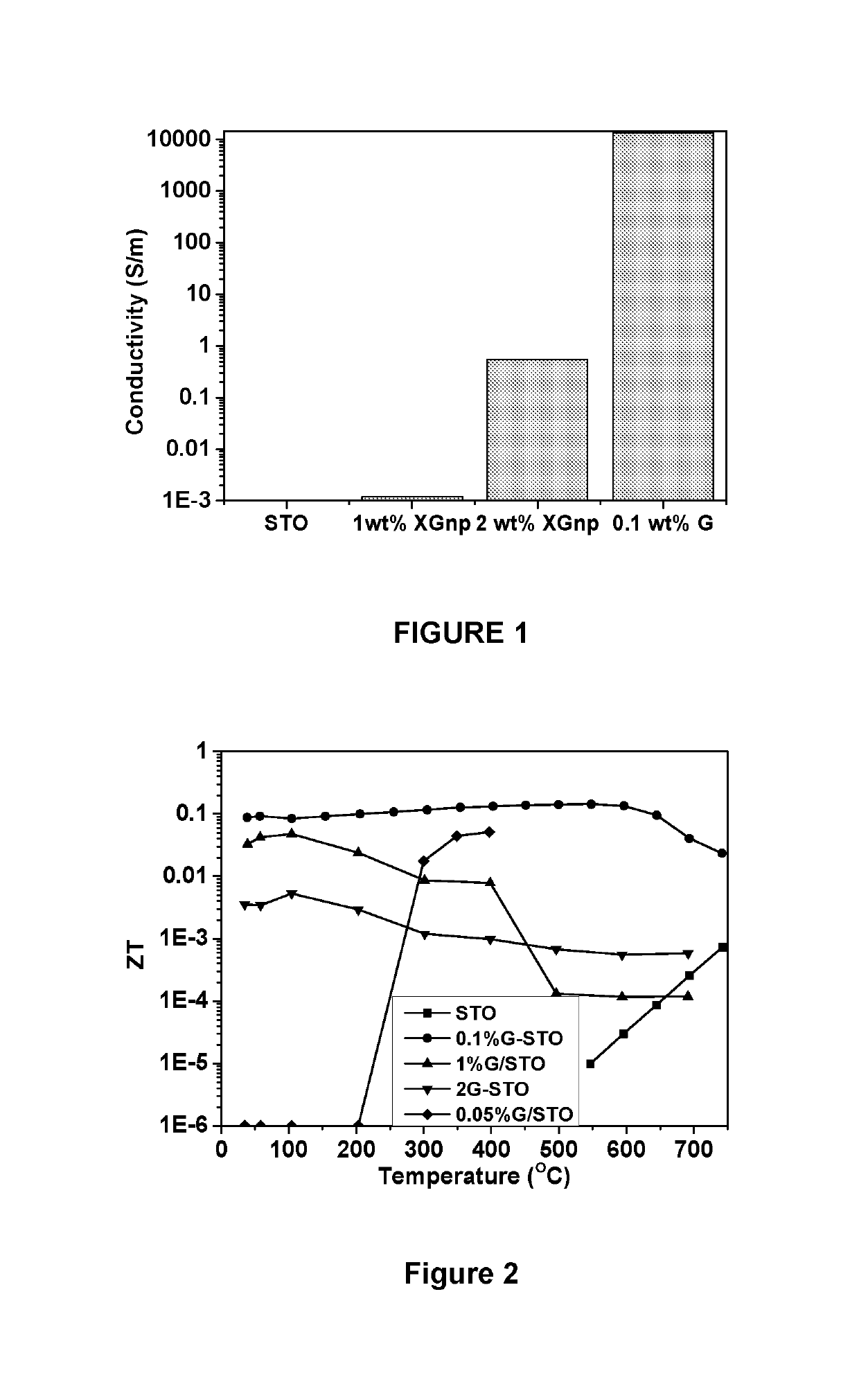
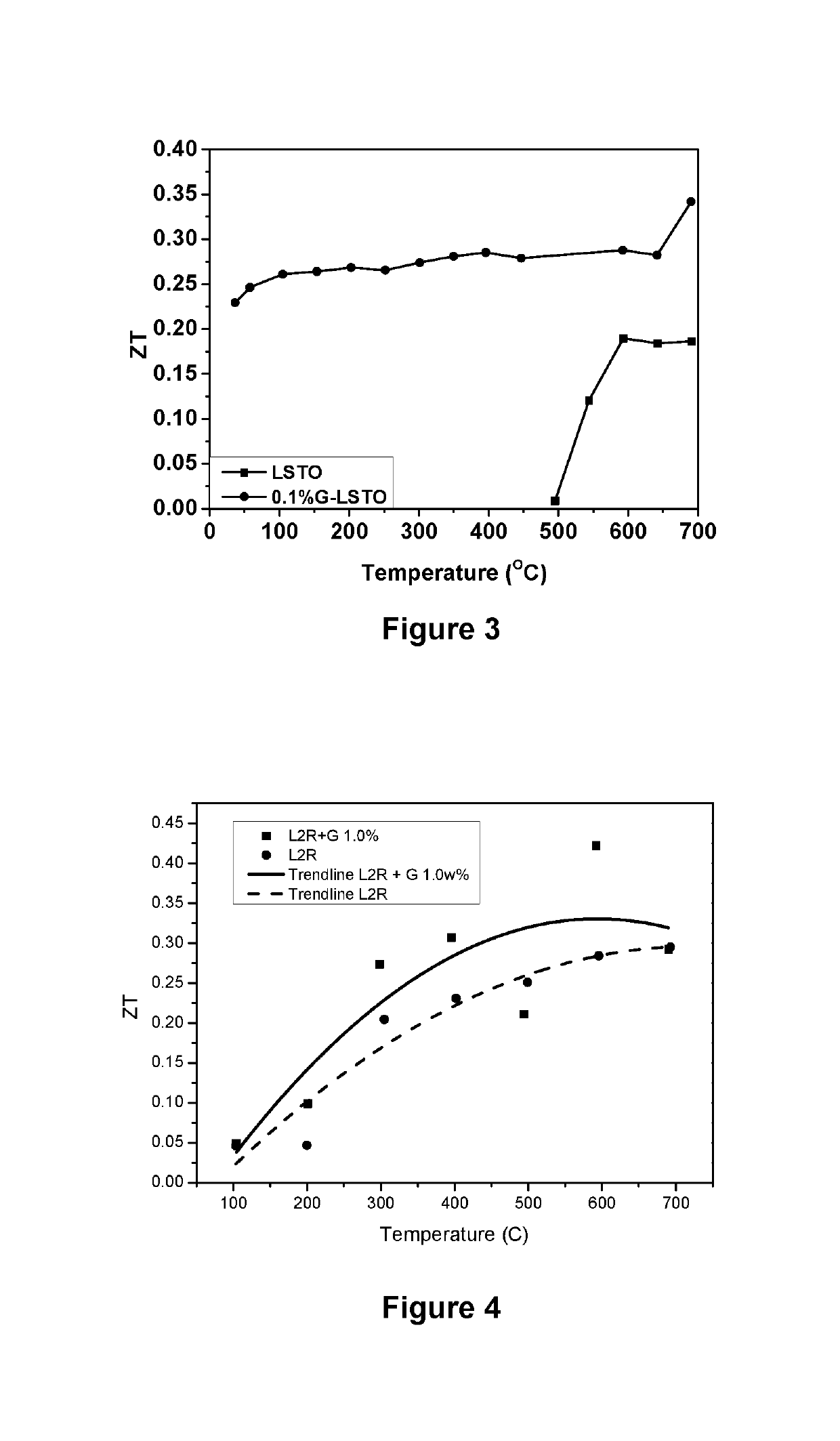
[0032]It has been found that the addition of graphene or modified graphene to thermoelectric metal oxide materials increases ZT. It has further been found that the ZT of the metal oxide becomes effective over a broader temperature range and at lower temperatures.
[0034]A further surprising benefit of some of the materials of the invention appears to reside in the fact that this improvement is manifested across a wide temperature range. For example, the present invention provides thermoelectric materials having operating temperatures which span several hundred degrees. Indeed, in some examples of the invention, materials demonstrate acceptable ZT values across more than 600° C. of temperature. Advantageously, certain materials according to the invention are able to exhibit acceptable ZT values extending to as low as 50° C., and some of those same materials are still able to provide a similar ZT level at 600° C. or 700° C. The ability to achieve an acceptable ZT value at a relatively low temperature such as 50° C. or 100° C. provide access to recovery of electrical power from thermal sources where it might not otherwise have been possible. Some materials of the present invention also show a substantially linear power generation response across a range of temperatures. This represents a large advantage in the materials of the invention because they may be used in a wide range of potential applications.
[0035]Furthermore, the smaller density of the materials of the invention compared with conventional thermoelectric materials enables lighter power generation devices to be produced. The materials of the invention have good power density and also exhibit a good thermal power output (the thermal power output is defined in p volts / K).

Problems solved by technology

The existing materials which exhibit sufficient ZT values are usually too heavy, too expensive, and / or too toxic to find general application though they remain of theoretical interest.
Consequently, the exploitation of these materials in various applications is limited not only by their ZT values but also by the range of temperature within which they operate.
These are effective for cooling applications and for low temperature waste heat recovery but they are confined to applications using such low operating temperatures and contain rare toxic elements.
These materials do not find broad application because they are limited to below 600° C. and are optimised at around 400° C.
These materials have been used in prototypes of automobile exhaust thermoelectric generators, but these materials, particularly the p-type, suffer from a fairly low ZT due to the high lattice thermal conductivity of the diamond structure.
The cost of the raw material is very high and is increasing dramatically.
These materials have the advantage of good ZT values but this advantage can be offset due to the fact that the materials tend to be heavy and are also toxic and / or an environmentally unfriendly.
There are reports of ZTs as high as 1.4 at 600° C. for these materials; however the preparation of these materials often requires high temperature and pressure.
Whilst cheaper than Bi2Te3 it is almost as dense (therefore weight penalty) and there are the same problems of high temperature stability and processing can be difficult.
However, producing high quality Mg2Si consistently continues to be a problem and there are questions about its high temperature stability.
They are made from non-toxic, naturally abundant, light cheap elements and they are stable at the elevated temperatures present in many heat recovery applications but unfortunately the thermoelectric properties of these oxides continue to be inferior to traditional metal materials.
This low efficiency is the reason that oxide based materials have failed to replace traditional alloys and thus limited the wide range of commercial applications that could be possible with these materials.

Method used


Image

  • Thermoelectric materials and devices comprising graphene
  • Thermoelectric materials and devices comprising graphene

Examples


example 1

[0145]Ca(NO3)2, Co(NO3)2.6H2O, La(NO3)3.6H2O, and citric acid can be used as raw materials. Mixtures of the above ingredients in the appropriate proportions to provide nominal compositions of Ca3Co4O9 and (La0.1Ca0.9)3Co4O9 can be thoroughly dissolved in distilled water, respectively, and then heated to form a transparent gel. The dried gel can be ground and calcined at 800° C. for 2 h to form the precursor powders. The ceramic bulk samples can be compacted in vacuum in a SPS apparatus. The powder precursors were sintered by spark plasma sintering (SPS) method at 900° C. for 5 min. The samples can then be forged in the same SPS apparatus by loading 750° C. predensified cylindrical samples with a diameter of 15 mm and a height of 5 mm into a die with inner diameter of 20 mm and heated up with a heating rate of 100° C. / min in vacuum to the preset deformation temperature of 900° C. A constant uniaxial load that corresponded to an initial compressive stress of 40 Mpa can be applied when...

example 2

[0146]Ceramic powders with nominal compositions Ca3Co4O9 (p-type) and Ca0.95Sm0.05MnO3 (n-type) can be synthesized from stoichiometric amounts of CaCO3, Co3O4, Sm2O3 and MnO2 by “solid state reaction”. The precursor powders can be mixed and calcinated twice at 900° C., for 12 h with intermediate grindings to obtain a homogeneous composition. The mixture powder can be first formed into a cylindrical pellet (24 mm diameter) or bars 4 mm×4 mm×35 mm) under 30 MPa using a compacting cell. The cobaltite samples can be sintered in air at 920° C., for 24 h. Polyvinyl alcohol can be used as a binder in the case of the manganite compaction due to the coarser starting particle size. The processing temperature of the n-type material can be 1350° C., 12 h. A platinum plate should be used between the sample and Al2O3 crucible to prevent the reaction between the material and the support.

example 3

[0147]For Ag-doped Ca3-xAgxCo4O9 (x=0, 0.1 and 0.3) polycrystalline samples, reagent grade CaCO3, Co2O3 and AgNO3 powders in the stoichiometric ratio can be mixed thoroughly and calcined in air at 1173 K for 12 h. Then the mixture can be reground, pressed into pellets and sintered at 1173 K for 36 h under an 02 flow with an intermediate grinding. The pellets can be pulverized manually for 1 h, and then the powders were cold pressed into disc-shaped pellets under a high pressure of 3 GPa with a special die. Finally, the above pellets can be sintered under 02 flow at 1173 K for 12 h.

[0148]For Ag-added Ca3CO4O9 ceramic composites, the prepared Ca3Co4O9 powders can be mixed with Ag2O powders in three different weigh ratios to Ca3Co4O9:3.5 wt %, 10 wt % and 20 wt %. (The Ag element concentration of 3.5 wt % and 10 wt % Ag-added samples will be equal to that of x=0.1 and 0.3 Ag-doped samples, respectively.) The mixed powders can also be cold pressed under 3 GPa and then sintered at 1173 K...


PUM

PropertyMeasurementUnit
temperatureaaaaaaaaaa

Abstract

Composite materials with thermoelectric properties and devices made from such materials are described. The thermoelectric composite material may comprise a metal oxide material and graphene or modified graphene. It has been found that the addition of graphene or modified graphene to thermoelectric metal oxide materials increases ZT. It has further been found that the ZT of the metal oxide becomes effective over a broader temperature range and at lower temperatures.

Description

CROSS-REFERENCE TO RELATED APPLICATIONS[0001]This application is a national stage application of International Application No. PCT / GB2014 / 050437 filed on Feb. 14, 2014 which claims priority to GB Application No. 1302556.4 filed on Feb. 14, 2013, the disclosures of each of which are hereby incorporated by reference in their entirety.[0002]This invention relates to composite materials with thermoelectric properties and devices made from such materials. The present invention is concerned with novel materials for use in thermoelectric generators. These materials can be used in power generation to convert waste heat into electrical power in a wide variety of different applications ranging from automotive applications to space exploration and satellite technology. The same materials can also be used in thermoelectric cooling devices such as refrigerators which transfer heat from one side of the materials to the other on the application of an electric current.BACKGROUND[0003]The generation...

Claims


Application Information

Patent Timeline
Patent Type & Authority Patents(United States)
IPC IPC(8): H01L35/22H01L35/26H01L35/34H01L35/12C04B35/01C04B35/453C04B35/47C04B35/645C25D9/02C01B32/19C01B32/194
CPCH01L35/22C01B32/19C01B32/194C04B35/01C04B35/016C04B35/453C04B35/47C04B35/645C25D9/02H01L35/12H01L35/26H01L35/34C04B2235/3208C04B2235/3213C04B2235/3237C04B2235/3267C04B2235/3275C04B2235/3284C04B2235/3298C04B2235/422C04B2235/5292C04B2235/652C04B2235/6581C04B2235/6585C04B2235/663C04B2235/666C04B2235/721C04B2235/80Y02P20/129C04B2235/3224C04B2235/3225C04B2235/3227C04B2235/3251C04B2235/3291C04B2235/424C04B2235/449C04B2235/6582H10N10/857H10N10/855H10N10/01H10N10/85
Inventor FREER, ROBERTNORMAN, COLINLIN, YUESRIVASTAVA, DEEPANSHUKINLOCH, IAN
Owner UNIV OF MANCHESTER
Learn More