BO-corrected sensitivity encoding magnetic resonance imaging

a technology of sensitivity encoding and magnetic resonance imaging, applied in the field of magnetic resonance imaging, can solve problems such as phase error that builds up, image folding, and unfolding process only deals

Active Publication Date: 2021-03-23
KONINKLJIJKE PHILIPS NV
View PDF14 Cites 1 Cited by
  • Summary
  • Abstract
  • Description
  • Claims
  • Application Information

AI Technical Summary

Benefits of technology

[0009]During a SENSE MRI imaging, magnetic resonance data (which may be also referred to as magnetic resonance imaging data) is acquired using multiple coil elements. The magnetic resonance data is used to create an image for each of the multiple coil elements. As described in the above mentioned review article by Pruessmann et. al., the images are acquired using a reduced field of view in comparison to the final reconstructed image. This use of reduced field of view accelerates the acquisition, but leads to so called image folding. The images for the each of the multiple coil elements are therefore referred to as a set of folded images.

Problems solved by technology

This use of reduced field of view accelerates the acquisition, but leads to so called image folding.
A difficulty is that the unfolding process only deals with folding artifacts that are due to the reduced field of view.
Inhomogeneities in the B0 field result in a phase error that builds up over the duration of a pulse repetition.
When the image is reconstructed this phase error results in an error in the location of spins that produced an MR signal.
For lower B0 field distortions this results in a shift or distortion in the image.
If the inhomogeneities in the magnetic field are great enough several locations can be mapped to the same location in an image, and this results in artifacts that resemble the folding artifacts due to the reduced field of view in SENSE MRI imaging.
For both larger and smaller B0 field distortions, the standard SENSE reconstruction will result in an improperly reconstructed SENSE MRI image.
The use of such a correction not only corrects for distortions in the in the images, but it may also have the side effect of correcting errors in the coil sensitivities due to inhomogeneities in the B0 magnetic field also.

Method used


Image

  • BO-corrected sensitivity encoding magnetic resonance imaging
  • BO-corrected sensitivity encoding magnetic resonance imaging
  • BO-corrected sensitivity encoding magnetic resonance imaging

Examples


Embodiment Construction

lass="d_n">[0064]Like numbered elements in these figures are either equivalent elements or perform the same function. Elements which have been discussed previously will not necessarily be discussed in later figures if the function is equivalent.

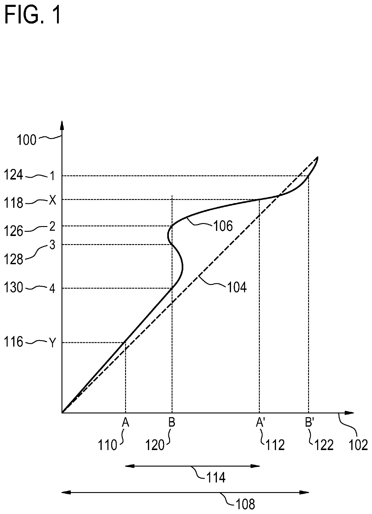
[0065]In MRI, particularly when using an Echo Planar Imaging (EPI) sequence, significant geometric distortions may occur due to local deviations of the magnetic field. This may be particularly seen close to metal implants or close to cavities, e.g. the ear or nose cavities—or, in general, with all tissue-to-air interfaces. In many cases, the distortion itself is clinically not very relevant nor disturbing.

[0066]However, when using SENSE, there may be indirect consequences of the distortion. At the ‘folding position’ relative to the distorted region (e.g. at a distance of half the field-of-view with SENSE_factor=2), artifacts may appear of the distorted region, even if that folding-position is rather free from distortion. This may for example ...


PUM


Abstract

A magnetic resonance imaging system (200, 300, 400) includes a radio-frequency system (216, 214) with multiple coil elements (214) for acquiring magnetic resonance data (264) and a memory (250) for storing machine executable instructions (260) and pulse sequence commands (262). The pulse sequence commands are configured for controlling the magnetic resonance imaging system to acquire the magnetic resonance data according to a SENSE imaging protocol. Execution of the machine executable instructions causes a processor (244) to: control (500) the magnetic resonance imaging system to acquire the magnetic resonance data using the pulse sequence commands; reconstruct (502) a set of folded magnetic resonance images (266) from the magnetic resonance data; calculate (504) a voxel deformation map (270) from a magnetic field inhomogeneity map; and calculate (506) a set of unfolding matrices (274) using a least partially a coil sensitivity matrix (272) for the multiple coil elements, wherein the set of unfolding matrices includes at least one modified unfolding matrix which is calculated at least partially using the a coil sensitivity matrix and the voxel deformation map. Undistorted magnetic resonance image data (276) is calculated (508) using the set of folded magnetic resonance images and the set of unfolding matrices.

Description

CROSS REFERENCE TO RELATED APPLICATIONS[0001]This application is a U.S. national phase application of International Application No. PCT / EP2017 / 071075 filed on Aug. 22, 2017, which claims the benefit of EP Application Serial No. 16185766.9 filed on Aug. 25, 2016 and is incorporated herein by reference.TECHNICAL FIELD[0002]The invention relates to magnetic resonance imaging, in particular to Sensitivity Encoding (SENSE) magnetic resonance imaging techniques.BACKGROUND OF THE INVENTION[0003]A large static magnetic field is used by Magnetic Resonance Imaging (MRI) scanners to align the nuclear spins of atoms as part of the procedure for producing images within the body of a patient. This large static magnetic field is referred to as the B0 field or the main magnetic field.[0004]One method of spatially encoding is to use magnetic field gradient coils. Typically there are three coils which are used to generate three different gradient magnetic fields in three different orthogonal directio...

Claims


Application Information

Patent Timeline
Patent Type & Authority Patents(United States)
IPC IPC(8): G01R33/561G01R33/565
CPCG01R33/5612G01R33/5611G01R33/56536G01R33/56554G01R33/56563
Inventor FUDERER, MIHADE WEERDT, ELWINERMES, JEAN-PIERRE FRANCISCUS ALEXANDER MARIA
Owner KONINKLJIJKE PHILIPS NV
Why Eureka
Try Eureka