
Heating coil, heat treatment apparatus, and heat treatment method for elongated workpiece

a heat treatment apparatus and workpiece technology, applied in heat treatment apparatus, electric/magnetic/electromagnetic heating, furnaces, etc., can solve the problems of difficult heat treatment of workpieces at high speed, limited proportion of coils facing workpieces, and increased electric power, so as to speed up heat treatment and reduce power consumption.

Active Publication Date: 2021-03-23
NETUREN CO LTD
View PDF17 Cites 0 Cited by
  • Summary
  • Abstract
  • Description
  • Claims
  • Application Information

AI Technical Summary

Benefits of technology

[0008]It is an object of the present invention to provide a heating coil, a heat treatment apparatus, and a heat treatment method that are capable of speeding up a heat treatment on a lateral surface of an elongated workpiece with low power consumption.

Problems solved by technology

Therefore, the area of the portion of the coil that faces the workpiece is limited, which makes it difficult to heat the workpiece at high speed.
In this case, however, the increased cross sectional area of the coil requires greater electric power, which deteriorates efficiency.
However, this results in a complex configuration of the heating coil.
As a consequence, an electric current path and a cooling fluid path through the coil also become complicated, which increases an output loss of the coil and makes it difficult to maintain a certain level of flow rate of cooling fluid.

Method used


Image

  • Heating coil, heat treatment apparatus, and heat treatment method for elongated workpiece
  • Heating coil, heat treatment apparatus, and heat treatment method for elongated workpiece
  • Heating coil, heat treatment apparatus, and heat treatment method for elongated workpiece

Examples


first example

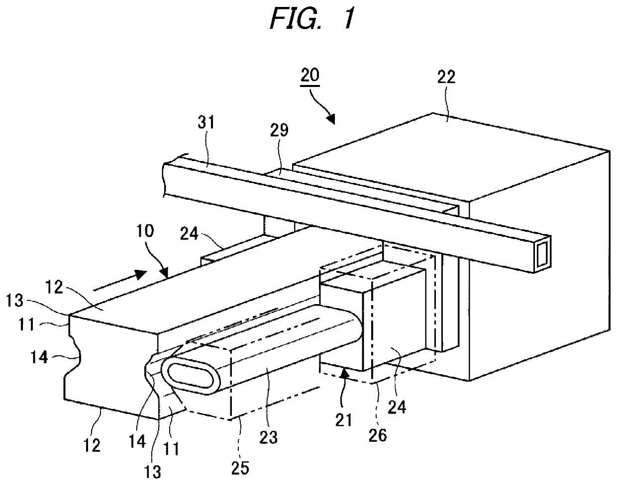
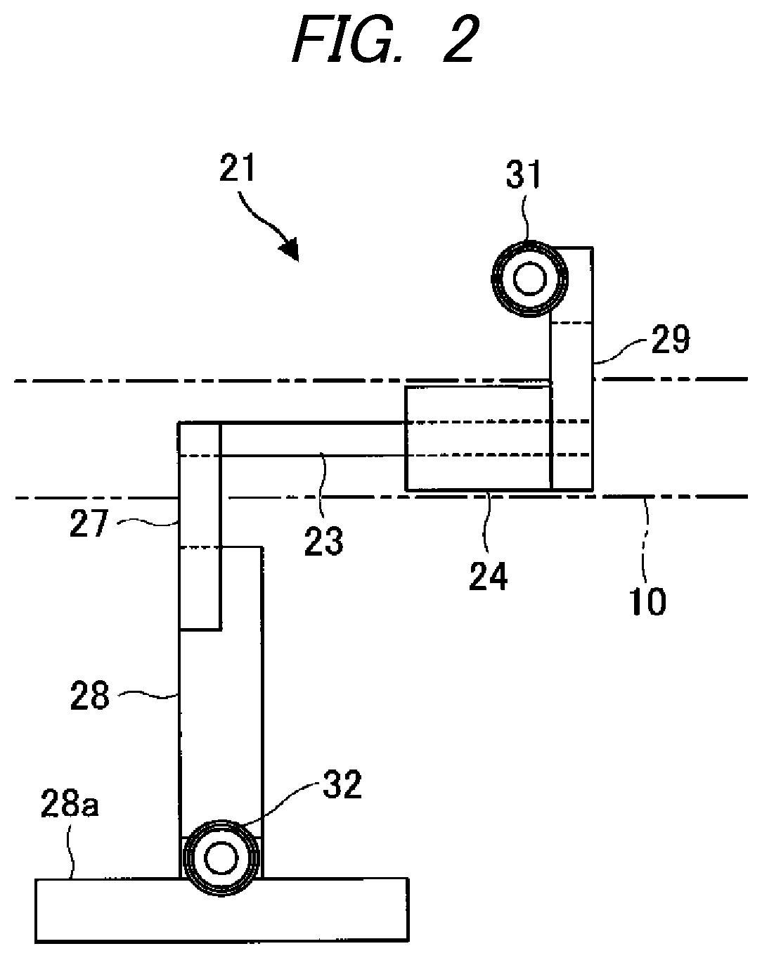
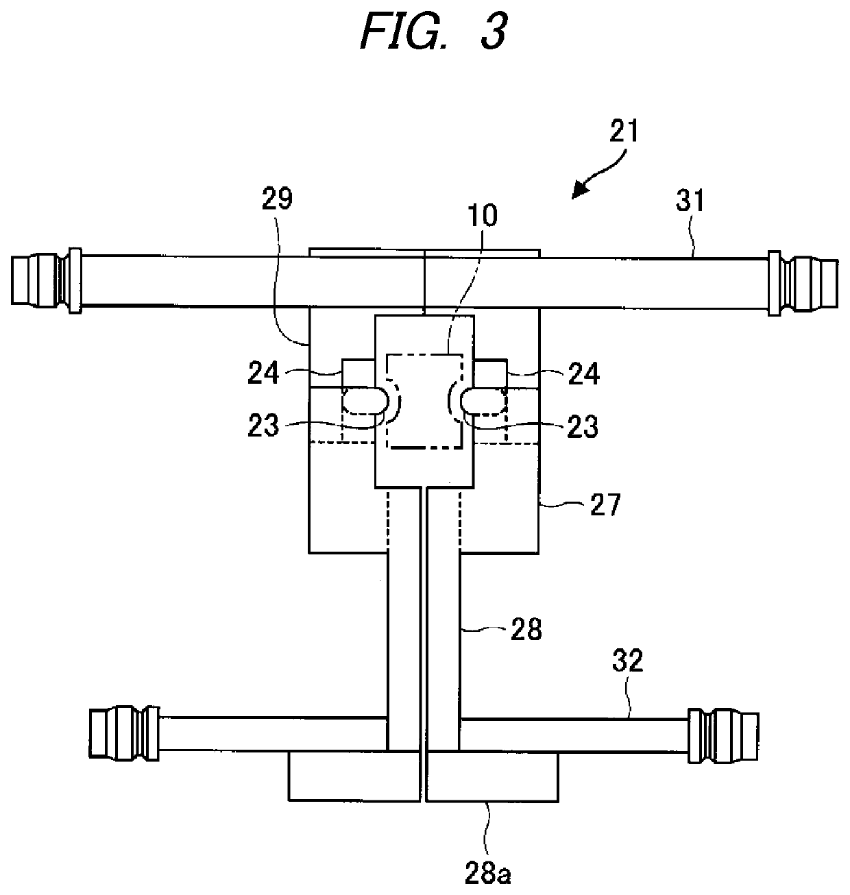
[0052]Induction heating and cooling were performed in the same manner as in a first reference example except that the heating coil 21 shown in FIG. 1 was used and electric power was supplied at a frequency of 10 kHz. As a result, the first lateral surfaces 11 and the recesses 14 were quenched in a suitable manner. An increase in the temperature of the cooling fluid for the heating coil 21 from an inlet side to an outlet side was 8° C.

second example

[0053]Induction heating and cooling were performed in the same manner as in a second reference example except that the heating coil 21 shown in FIG. 1 was used and a feed rate of the workpiece 10 was increased by 30%. As a result, the first lateral surfaces 11 and the recesses 14 were quenched in a suitable manner. An increase in the temperature of the cooling fluid for the heating coil 21 from an inlet side to an outlet side was 12.5° C.

first reference example

[0054]A workpiece 10 having a substantially rectangular cross section with recesses 14 provided on the pair of first lateral surfaces 11 was prepared, an angled heating coil was prepared and disposed in a heating region as shown in FIG. 7, and induction heating and cooling were carried out by feeding electric power to the heating coil at a frequency of 25 kHz. As a result, the first lateral surfaces 11 and the recesses 14 were quenched in a suitable manner. An increase in the temperature of the cooling fluid for the heating coil from an inlet side to an outlet side was 21° C.


PUM

PropertyMeasurementUnit
frequencyaaaaaaaaaa
temperatureaaaaaaaaaa

Abstract

A heating coil of a heat treatment apparatus is configured to inductively heat an elongated workpiece having a recessed lateral surface. The heating coil includes a base conductor and a projected conductor. A width of the projected conductor is narrower than a width of the base conductor. The projected conductor is arranged to project toward the recess from a position of the base conductor. The base conductor and the projected conductor are arranged to extend in a longitudinal direction of the workpiece. A heat treatment apparatus includes a cooling section and the heating coil. A heat treatment method uses the heating coil described above.

Description

TECHNICAL FIELD[0001]The invention relates to a heating coil for heating a recessed lateral surface of an elongated workpiece along a longitudinal direction of the workpiece, and also to a heat treatment apparatus and a heat treatment method for heat-treating the recessed lateral surface of the elongated workpiece.BACKGROUND ART[0002]Related art heating coils are configured such that, when heat-treating an elongated workpiece having a recessed lateral surface, the recessed lateral surface is heated without heating other lateral surfaces of the workpiece.[0003]For example, JP3924084B2 discloses a heating coil having rod-shaped conductors extending in a widthwise direction of an elongated workpiece orthogonal to the longitudinal direction of the workpiece, and protrusions formed on the conductors so as to be inserted into respective recesses on the lateral surfaces, thereby inductively heating the entire recessed lateral surfaces of the workpiece while relatively moving the workpiece ...

Claims


Application Information

Patent Timeline
Patent Type & Authority Patents(United States)
IPC IPC(8): H05B6/40C21D1/42C21D1/667C21D1/10H05B6/10H05B6/42C21D9/00
CPCH05B6/40C21D1/10C21D1/42C21D1/667C21D9/0062H05B6/101H05B6/104H05B6/42Y02P10/25
Inventor TANAKA, YOSHIMASASUGIYAMA, YUTAKA
Owner NETUREN CO LTD
Learn More