Display device
a display device and metal line technology, applied in the field of flat display technology, can solve the problems of inferior stability of metal lines in the outer layer of double-layer metal lines to the metal lines in the inner layer, and the difference in the stability of metal lines may affect the stability of subsequent display products, so as to achieve the effect of prolonging the length
- Summary
- Abstract
- Description
- Claims
- Application Information
AI Technical Summary
Benefits of technology
Problems solved by technology
Method used
Image
Examples
first embodiment
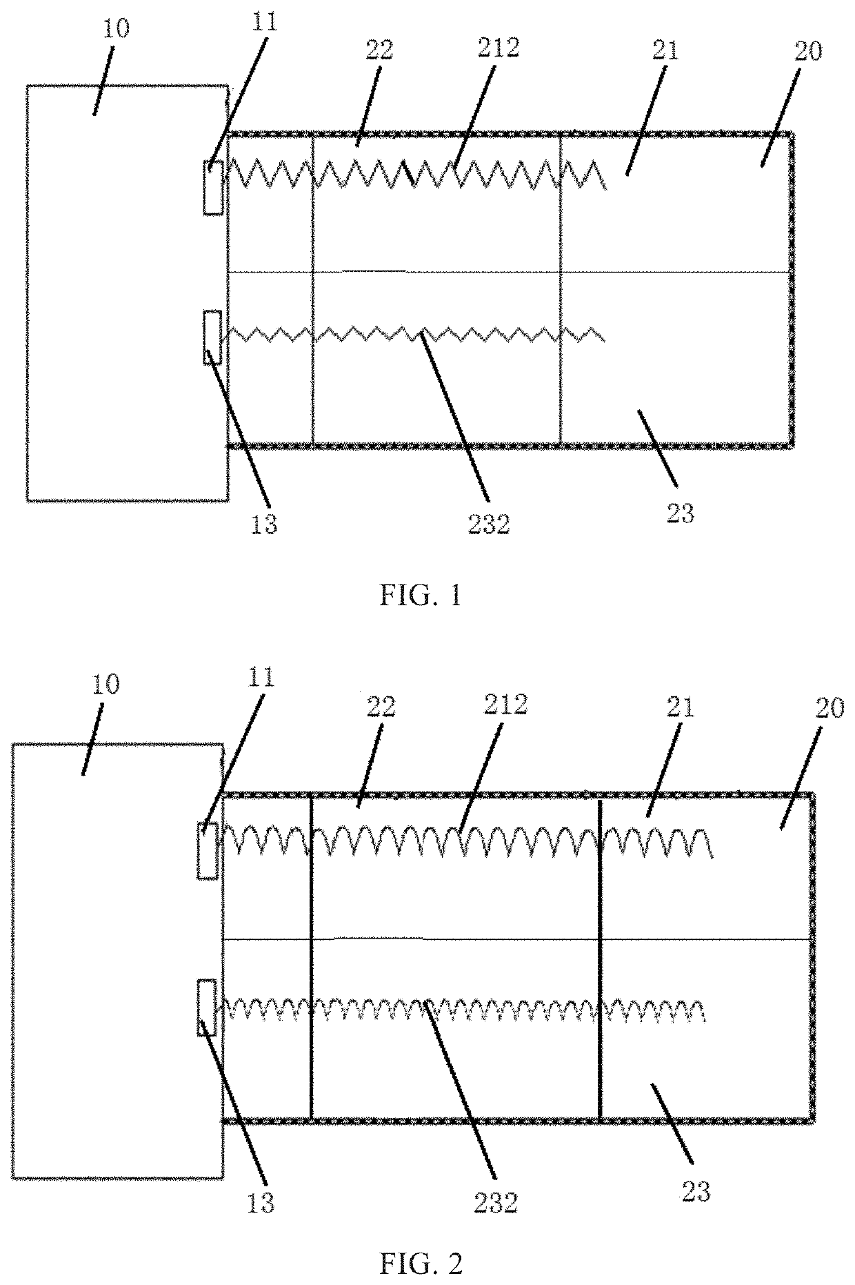
[0029]Please refer to FIG. 1 illustrating a schematic diagram of a display device according to the present disclosure. The display device includes a display panel 10 and a flexible substrate 20. The flexible substrate 20 includes a metal line arranged in a first layer and a metal line arranged in a second layer. To elaborate the flexible substrate 20, a first insulating layer over the second layer and the first layer over the second layer are not illustrated in FIG. 1.
[0030]A first pad 11 and a second pad 13 are arranged on the display panel. The first pad 11 and the second pad 13 may be, but are not limited to, arranged in the same layer. The flexible substrate 20 includes a first layer 21, a first insulating layer (not illustrated), and a second layer 23. The first layer 21 is arranged on the flexible substrate 20. A first metal line 212 with a first shape is arranged in the first layer 21 and electrically connected to the first pad 11 and a printed circuit board (PCB) (not illust...
second embodiment
[0033]Please refer to FIG. 2 illustrating a schematic diagram of a display device according to the present disclosure. The display device includes a display panel 10 and a flexible substrate 20. To elaborate the flexible substrate 20, a first insulating layer over the second layer and the first layer over the second layer are not illustrated in FIG. 2.
[0034]A first shape of a first metal line 212 is shaped as a curve. A second shape of a second metal line 232 is also shaped as a curve. However, the bending curvature of the first shape is greater than the bending curvature of the second shape, thereby ensuring that the length of the first metal line 212 in a bending area 22 is greater than the length of the second metal line 232.
third embodiment
[0035]Please refer to FIG. 3 illustrating a schematic diagram of a display device according to the present disclosure. The display device includes a display panel 10 and a flexible substrate 20. To elaborate the flexible substrate 20, a first insulating layer over the second layer and the first layer over the second layer are not illustrated in FIG. 3.
[0036]A first shape of a first metal line 212 is shaped as a waveform. A second shape of a second metal line 232 is also shaped as a waveform. However, the peak of the first shape is greater than the peak of the second shape, thereby ensuring that the length of the first metal line 212 in a bending area 22 is greater than the length of the second metal line 232.
[0037]In the above embodiment, each of the first metal line 212 and the second metal line 232 has the same shape, but differ in parameters of specific shapes, thereby ensuring the length of the first metal line 212 in the bending area 22 is greater than the length of the second ...
PUM
 Abstract
Description
Claims
Application Information
 - R&D
- Intellectual Property
- Life Sciences
- Materials
- Tech Scout
- Unparalleled Data Quality
- Higher Quality Content
- 60% Fewer Hallucinations
Browse by: Latest US Patents, China's latest patents, Technical Efficacy Thesaurus, Application Domain, Technology Topic, Popular Technical Reports.
© 2025 PatSnap. All rights reserved.Legal|Privacy policy|Modern Slavery Act Transparency Statement|Sitemap|About US| Contact US: help@patsnap.com


