Systems and methods for an efficient, rechargeable glowstick

a rechargeable, glowstick technology, applied in the direction of lighting and heating apparatus, lighting support devices, and lanternescence, can solve the problems of not being able to have a concentrated light source, and achieve the effect of positive resistance to the rotation of the cap

Active Publication Date: 2021-04-06
NITE IZE INC
View PDF17 Cites 3 Cited by
  • Summary
  • Abstract
  • Description
  • Claims
  • Application Information

AI Technical Summary

Problems solved by technology

Ordinarily it is not desirable to have a concentrated light source, since such light sources may be blinding in low light conditions.

Method used


Image

  • Systems and methods for an efficient, rechargeable glowstick
  • Systems and methods for an efficient, rechargeable glowstick
  • Systems and methods for an efficient, rechargeable glowstick

Examples


Embodiment Construction

[0020]Certain terminology is used herein for convenience only and is not to be taken as a limitation on the embodiments of the systems and methods for an efficient, rechargeable glow stick. In the embodiments shown, the glowstick includes a uniquely oriented such that it abuts the light sources extremely closely. In many embodiments, it is desirable to have a light source that is in contact with or virtually in contact with the light source, in most cases an LED.

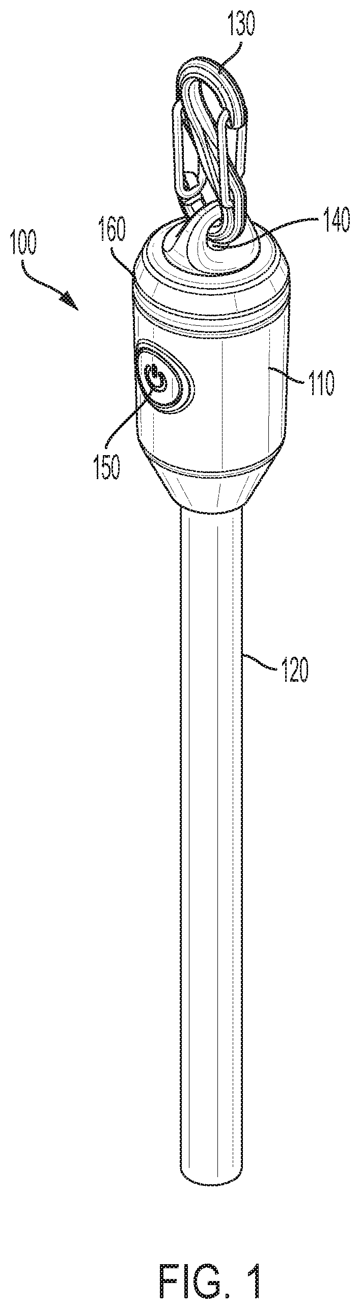
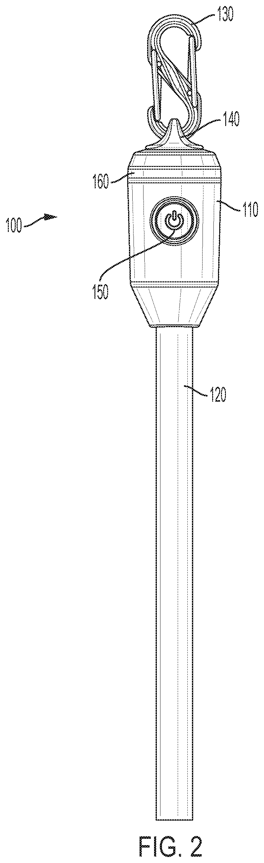
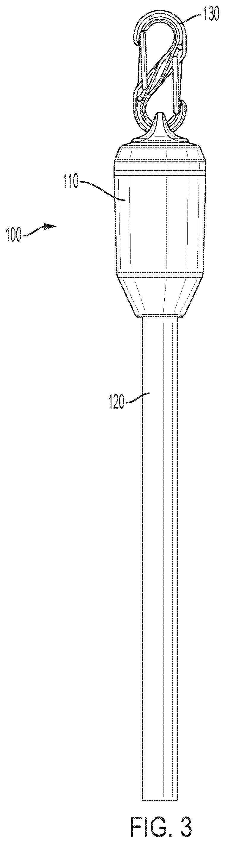
[0021]FIG. 1 shows one embodiment of an enhanced glowstick 100. Glowstick 100 includes a lighting module 110, a polymer stick portion 120, and carabineer 130. Polymer stick portion 120 is typically composed of transparent or translucent TPU (Thermoplastic polyurethane) or similar material. Lighting module 110 includes circuitry, light sources, and power sources that provide light to polymer stick portion 120. Carabineer 130 provides for attachment of the device to various connectors such as coats, backpacks, etc. Lighting mo...


PUM

PropertyMeasurementUnit
lengthaaaaaaaaaa
widthaaaaaaaaaa
resistanceaaaaaaaaaa

Abstract

A glowstick includes a lighting module, the lighting module including a light source having a primary direction of emission. The glowstick further includes a polymer rod, the polymer rod interfaced with the lighting module, the polymer rod having a length, a depth, and a width, wherein the length is greater than the depth and the length is greater than the width, the polymer rod proximate to the light source such that the primary direction of emission of the light source is aligned with the length of the polymer rod.

Description

BACKGROUND[0001]Visibility is an important safety concern in many scenarios. Ordinarily it is not desirable to have a concentrated light source, since such light sources may be blinding in low light conditions. A single point source of light may not be large enough to be noticeable to parties at a lower level, so it is desirable to have a light defusing mechanism, in order to light a larger area at a lower light level.BRIEF SUMMARY[0002]In one embodiment, a glowstick includes a lighting module, the lighting module including a light source having a primary direction of emission. The glowstick further includes a polymer rod, the polymer rod interfaced with the lighting module, the polymer rod having a length, a depth, and a width, wherein the length is greater than the depth and the length is greater than the width, the polymer rod proximate to the light source such that the primary direction of emission of the light source is aligned with the length of the polymer rod. Alternatively,...

Claims


Application Information

Patent Timeline
Patent Type & Authority Patents(United States)
IPC IPC(8): F21L4/08F21K2/08F21V21/088F21L14/02F21Y103/00F21V23/00
CPCF21L4/08F21K2/08F21L14/026F21V21/0885F21V23/005F21Y2103/00
Inventor ORMSBEE, BOWDENLESPERANCE, LEO
Owner NITE IZE INC
Why Eureka
Try Eureka