Pericardiocentesis needle guided by cardiac electrophysiology mapping

a technology of electrophysiology mapping and pericardiocentesis, which is applied in the field of pericardiocentesis needles and other interventional devices, can solve the problems of difficult transthoracic echo or intravascular echo, radiation exposure of both patient and operator, and inability to readily access ct/mri in the cardiac catheterization lab

Active Publication Date: 2021-04-13
KUSUMOTO WALTER
View PDF38 Cites 2 Cited by
  • Summary
  • Abstract
  • Description
  • Claims
  • Application Information

AI Technical Summary

Benefits of technology

[0014]The electrode or other sensor on the needle causes the location of the electrode relative to adjacent cardiac structures to be visualized on the display of the EP mapping system. By placing the electrode on the needle a known distance from a tip of the needle, and by knowing the orientation of the needle, the precise location of the tip of the needle can be known and visualized on the EP mapping system display. Knowing orientation of the needle can occur by having multiple electrodes on the needle, one distal and one proximal, so that the orientation of the needle is merely a line segment between the position of the two electrodes, or can be ascertained in some other fashion, such as by having a needle orientation sensor placed on the needle itself or other sensor physically attached to the needle. In one embodiment one of the electrodes can be the tip of the needle itself. By visualizing on the display the location of the tip of the pericardiocentesis needle in real time, a surgeon or other medical professional can precisely place the tip of the pericardiocentesis needle where desired relative to adjacent cardiac structures.
[0016]Accordingly, a primary object of the present invention is to provide a pericardiocentesis needle or other transcutaneous interventional device which is fitted with electrodes are other sensors so that it can be visualized through an EP mapping system display for most accurate, reliable and safe placement of the tip of the needle or other device.
[0018]Another object of the present invention is to provide a method for more effectively performing pericardiocentesis procedures, especially after pericardial fluid has been reduced.

Problems solved by technology

Echo guidance for pericardiocentesis has become a standard, however there are difficulties in performing transthoracic echo or intravascular echo while simultaneously directing a pericardiocentesis needle.
Fluoroscopy is sometimes utilized, but exposes both patient and operator to radiation.
CT and MRI guidance have been reported, however would require access to CT / MRI which may not be readily available in the cardiac catheterization lab.
This situation is a more difficult technique for the operator, and possibly has increased risk of catastrophic complications.

Method used


Image

  • Pericardiocentesis needle guided by cardiac electrophysiology mapping
  • Pericardiocentesis needle guided by cardiac electrophysiology mapping
  • Pericardiocentesis needle guided by cardiac electrophysiology mapping

Examples


Embodiment Construction

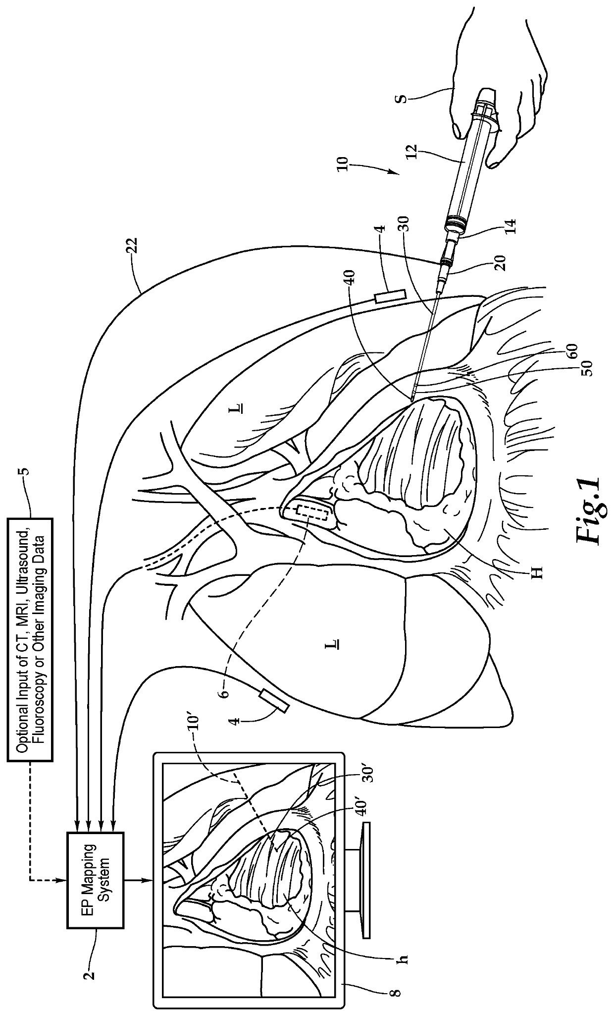
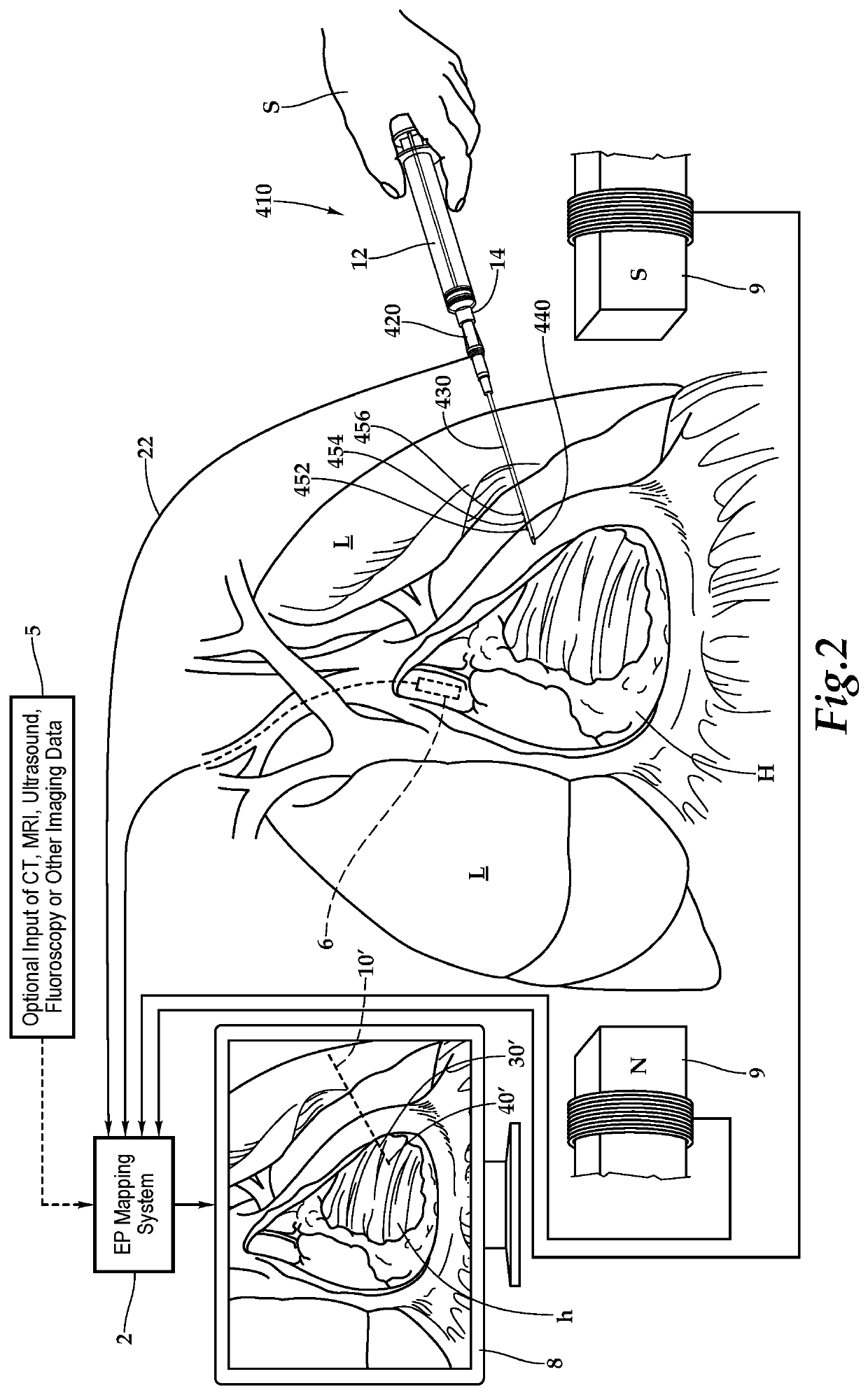
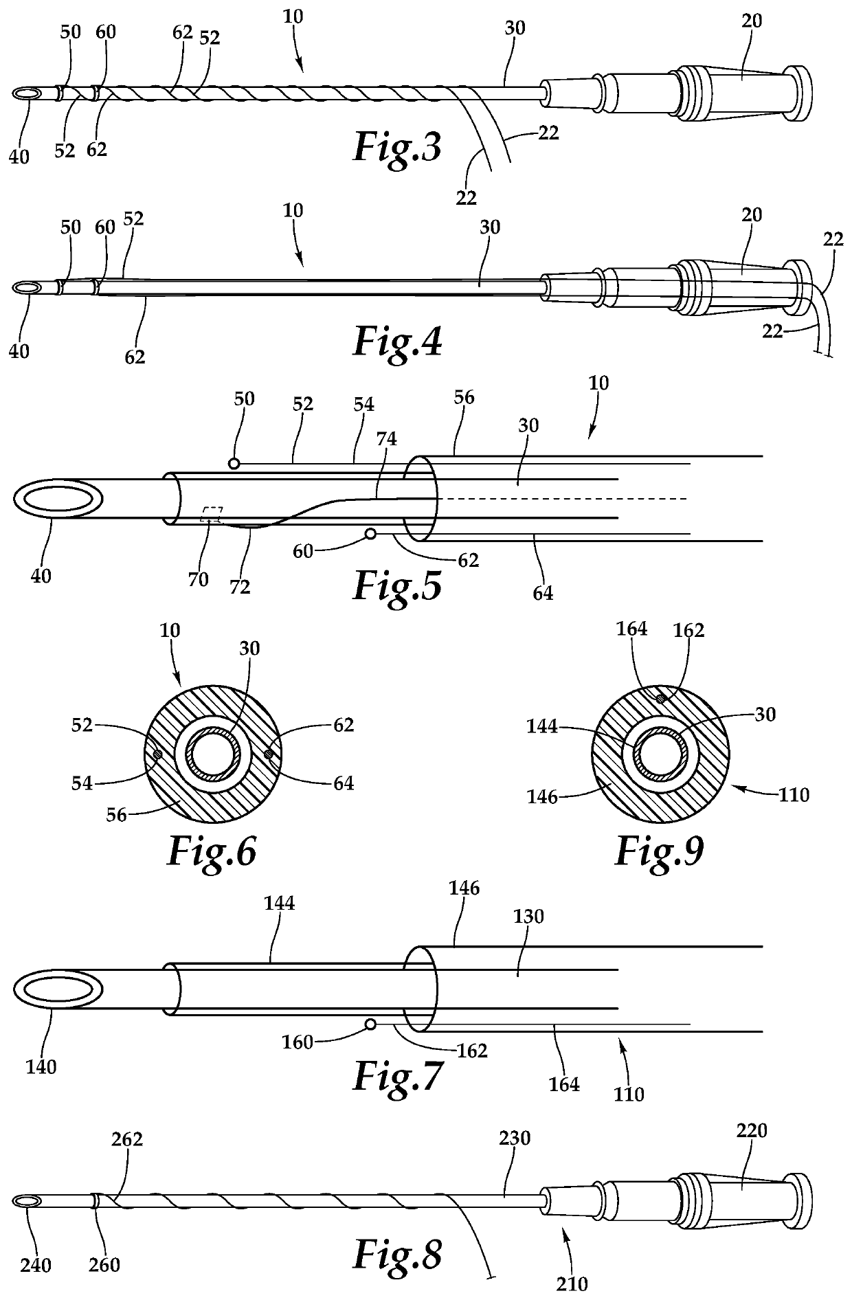
[0047]Referring to the drawings, wherein like reference numerals represent like parts throughout the various drawing figures, reference numeral 10 is directed to a pericardiocentesis needle (FIGS. 1-6 and 17) which provides one form of a transcutaneous medical device with sensors, such as electrodes 50, 60, on the needle 10 to cause the needle 10 to be visualizable on a display 8 of an electrophysiology (EP) mapping system 2. The needle 10 or other medical device can thus be accurately placed into spaces such as the pericardium while a tip 40 of the needle 10 can be visualized on the display 8, to assist in navigation of the needle 10 to a desired position, especially for the tip 40.

[0048]In essence, and with particular reference to FIG. 1, basic details of the needle 10 and associated EP mapping system 2 as modified by one embodiment of this invention, is described. The EP mapping system 2 includes multiple surface electrodes 4, as well as intra-cardiac electrodes 6 (and optionally...


PUM


Abstract

The pericardiocentesis needle is fitted with sensors, such as at least one electrode or at least one magnetic field sensor, and preferably both a proximal and a distal electrodes or multiple magnetic field sensors. These electrodes or other sensors are coupled to an electrophysiology mapping system configured to display cardiac structures on a display. The electrodes or other sensors on the needle cause a position, and preferably also orientation, of the needle, and especially the tip of the needle, to be visualized on a display of the electrophysiology mapping system, in accurate position relative to adjacent cardiac structures. In other embodiments other transcutaneous devices such as dilators and sheaths can be similarly fitted with electrodes or other sensors for visualization of such other devices within a display of an EP mapping system.

Description

CROSS-REFERENCE TO RELATED APPLICATIONS[0001]This application claims benefit under Title 35, United States Code § 119(e) of United States Provisional Application No. 62 / 398,394 filed on Sep. 22, 2016 and United States Provisional Application No. 62 / 516,556 filed on Jun. 7, 2017.FIELD OF THE INVENTION[0002]The following invention relates to pericardiocentesis needles and other interventional devices, including dilators and sheaths, which are modified to include sensors thereon so that the position of the needle or other interventional device can be visualized subcutaneously during a cardiac procedure using cardiac electrophysiology mapping systems. More particularly, this invention relates to needles and similar interventional devices which are fitted with one or more electrodes or one or more magnetic field sensors so that the needles or other interventional devices can be displayed in an accurate position (and preferably also orientation) within an electrophysiology mapping system ...

Claims


Application Information

Patent Timeline
Patent Type & Authority Patents(United States)
IPC IPC(8): A61B5/06A61B34/20A61B5/287A61B5/00A61B5/055
CPCA61B5/065A61B5/062A61B5/287A61B5/6848A61B5/6869A61B5/7445A61B34/20A61B5/055A61B5/063A61B5/743A61B5/7425A61B2034/2053
Inventor KUSUMOTO, WALTER
Owner KUSUMOTO WALTER
Why Eureka
Try Eureka