
Tip adjustable stylet

a technology of adjustable stylets and tips, which is applied in the direction of catheters, tracheal tubes, guide wires, etc., to achieve the effect of smooth surface and convenient alignmen

Active Publication Date: 2021-04-13
SUN YANG
View PDF7 Cites 2 Cited by
  • Summary
  • Abstract
  • Description
  • Claims
  • Application Information

AI Technical Summary

Benefits of technology

The present invention is an articulating stylet that can be inserted and positioned inside an ET to perform various functions. The device has a distal portion that is positioned outside of the ET's distal aperture before the device can perform its function. The distal portion of the device is positioned outside of the ET's distal aperture and can be manipulated by an operator from the proximal end of the device. The device has a flexible bendable segment that can be bended into different angles and curves to navigate the obstacles of a patient's airway and be moved toward the vocal cords opening. The position of the tip segment is controlled by the tension on the retracting string, location and bendability of the two bendable points, flexibility and length of the first and second bending sections of the bendable segment, and position of the bendable segment inside the ET lumen. The device enables an operator to move the distal tip in front of and through the vocal cords by pushing or pulling the control ring at the proximal end of the bendable member.

Problems solved by technology

However in many clinical scenarios, often time a medical practitioner needs to reach or examine a patient's and animal's narrow body space or detoured passages which could not be normally reached by a human hand or a straight shaped equipment.

Method used


Image

  • Tip adjustable stylet
  • Tip adjustable stylet
  • Tip adjustable stylet

Examples


first embodiment

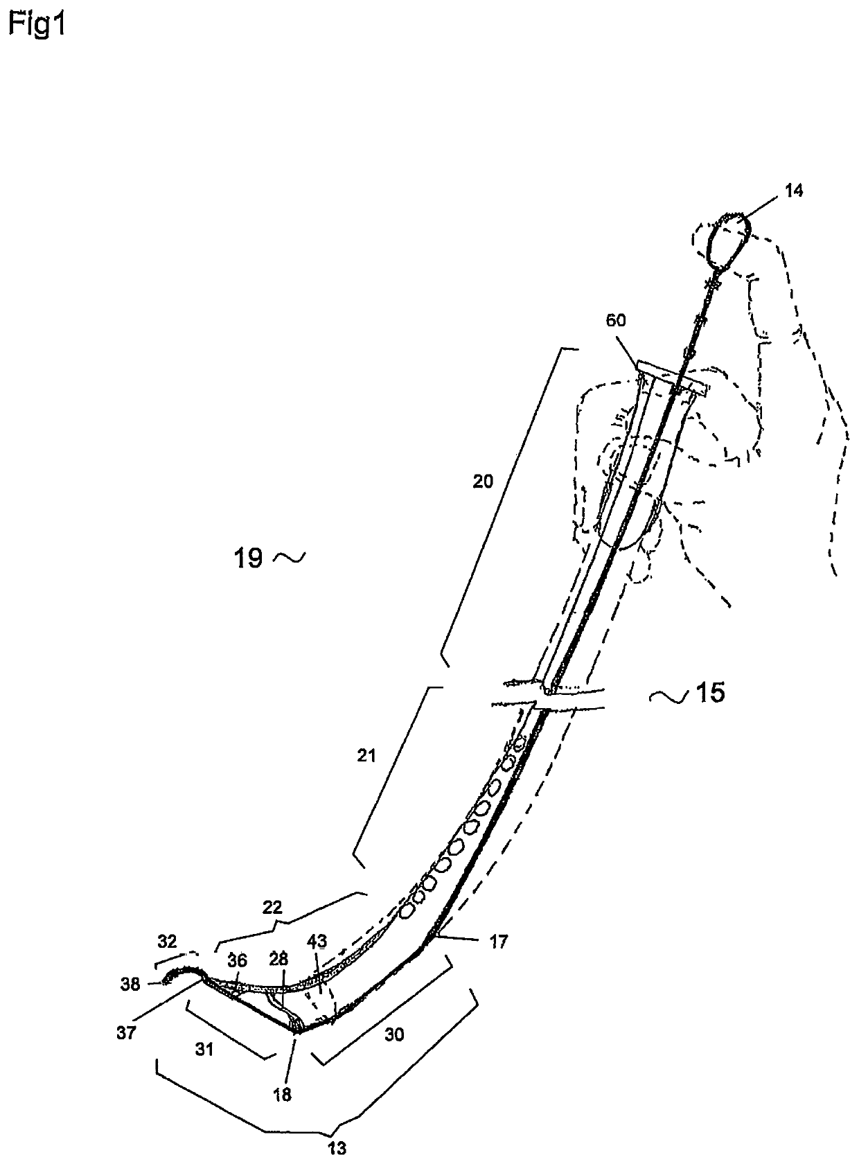
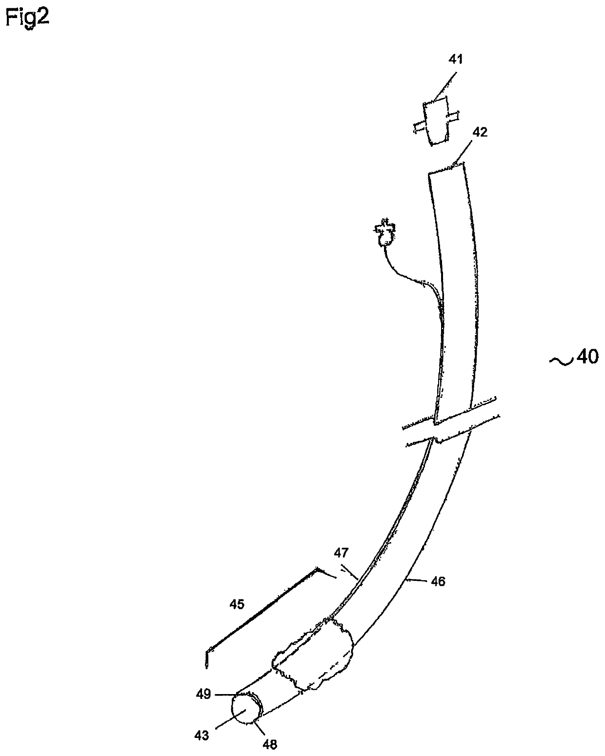
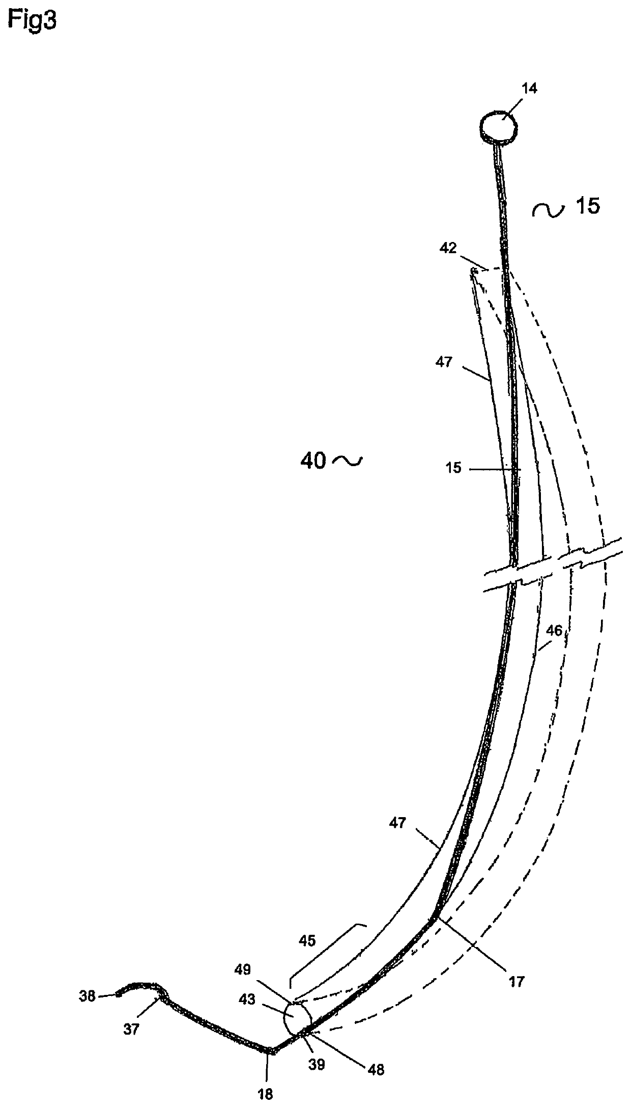
[0033]Referring to FIG. 1, shown is exemplary of the present invention in set-up configuration or set-up position after the stylet device inserted into an ET. FIG. 1 shows a left side view of the device being assembled in set-up position, which means the device has been inserted in to an ET 40 and the ET 40 has been held and not able to move up and down over the device, and not able to move forward and backward during the operation. The ET 40 and device together are ready to be inserted into patient's throat. From FIG. 1 to FIG. 8, the bendable member is a rod 15.

[0034]To prepare to use the device, an operator will lubricate bendable segment 13, middle segment 12 of the rod 15, and the distal retracting segment 22 of the retracting string 19. A length of the distal portion of the retracting string 19 and the rod 15 are inserted into an ET 40 with the edge of the ET distal aperture 43 matching a loading reference point 39. The loading reference point 39 is a symbol or mark on the ben...

second embodiment

[0070]FIG. 8, referring to second embodiment, at the distal end of the middle segment 12 of the rod 15 before continue with the bendable segment 22, a short segment of backward stem 80 has been configured which is continuation of the middle segment but turn posteriorly. The turning point 81 is anteriorly positioned against the anterior wall of an ET 40. The distal end of the backward stem 80 continues with the proximal end of the bendable segment 13 of the rod 15, also called bendable junction 17. The function of the bendable junction 17 is same as previously described embodiment. It will only be significantly bent during the third push, or after third push. The purpose of this design is alternative way to ensure at least most of the bendable segment 13 touch the ET posterior wall 46 during the first and second stage push, thereby does not move to anteriorly and possibly tangling with the retracting string 19. In a further alternative embodiment the intersegment 28 in the previously...

third embodiment

[0072]Two modifications can be made to first embodiment to make the device to have capability to carry fiber-optic-scope probe to have its own “vision”. FIG. 9a, 9b, 9c, referring to third embodiment, comprises the basic components same as first embodiment, a retracting string 19, a control handle 66 and an intersegment 28. All these three basic components have same configuration and functions. However the elongated bendable member 15 is modified as a flexible elongated shell shape to carry a fiber-optic scope probe, call bendable shell 85. This embodiment will also be assembled with an ET or tubular structure in the same way as the first embodiment.

[0073]In third embodiment, the bendable member 85 will also comprise a proximal segment, a middle segment, a bendable segment 75 and a tip segment 73 and has same length as the first embodiment. A control ring 14 is attached to the proximal end of the proximal segment. The bendable member has same two bendable points which is bending sec...


PUM


Abstract

Present invention is a tip adjustable stylet to be inserted into a tubular structure and to be pushed out its distal aperture to form curvatures. The device comprises a bendable member, a retracting string, an intersegment and a control handle. The bendable member has a control ring at its proximal end and a tip at its distal end. An operator can push the bendable member distally from the proximal end along the lumen of the tubular structure. Predetermined extensibility and length of the retracing string limit distance of the bendable member being pushed and hold the distal portion of the bendable member backward when the bendable member is been pushed forward outside of the tubular structure's distal aperture, thereby to bend the distal portion of the bendable member into the curves therefore to move its tip to a target location, such as patient's vocal cords opening.

Description

BACKGROUND[0001]Endotracheal tubes, brief as ET, have been utilized in a wide variety of medical specialties in past decades for airway management. Many intubation tools have been developed to effectively insert an endotracheal tube into a patient's trachea. An intubation process can often be difficulty because of the contours and obstacles encountered in a patient's airway. A patient's airway anatomy varies from patient to patient. As the endotracheal tubes are generally made to a standard curvature, it is often necessary to impart a greater bend to the tip of the tube in order to be inserted into a trachea. Many prior art devices have been developed to try to resolve these problems. One of the examples is a metal malleable stylet which can be inserted into an endotracheal tube and be bent at a desirable curvature by an operator before starting intubation process, but the operator will not be able to change the curvature of the stylet as needed during the intubation unless the endo...

Claims


Application Information

Patent Timeline
Patent Type & Authority Patents(United States)
IPC IPC(8): A61M16/04A61M25/09
CPCA61M16/0488A61M16/0418A61M2025/0915A61M25/0147
Inventor SUN, YANG
Owner SUN YANG
Learn More