
Bearing device for vehicle wheel

a technology for bearings and wheels, applied in the direction of roller bearings, mechanical devices, transportation and packaging, etc., can solve the problems of shortening the life of bearings of bearings and increasing friction torque of bearings, so as to increase the rigidity of the dam section, and increase the effect of damming up muddy water

Active Publication Date: 2021-04-13
NTN CORP
View PDF8 Cites 1 Cited by
  • Summary
  • Abstract
  • Description
  • Claims
  • Application Information

AI Technical Summary

Benefits of technology

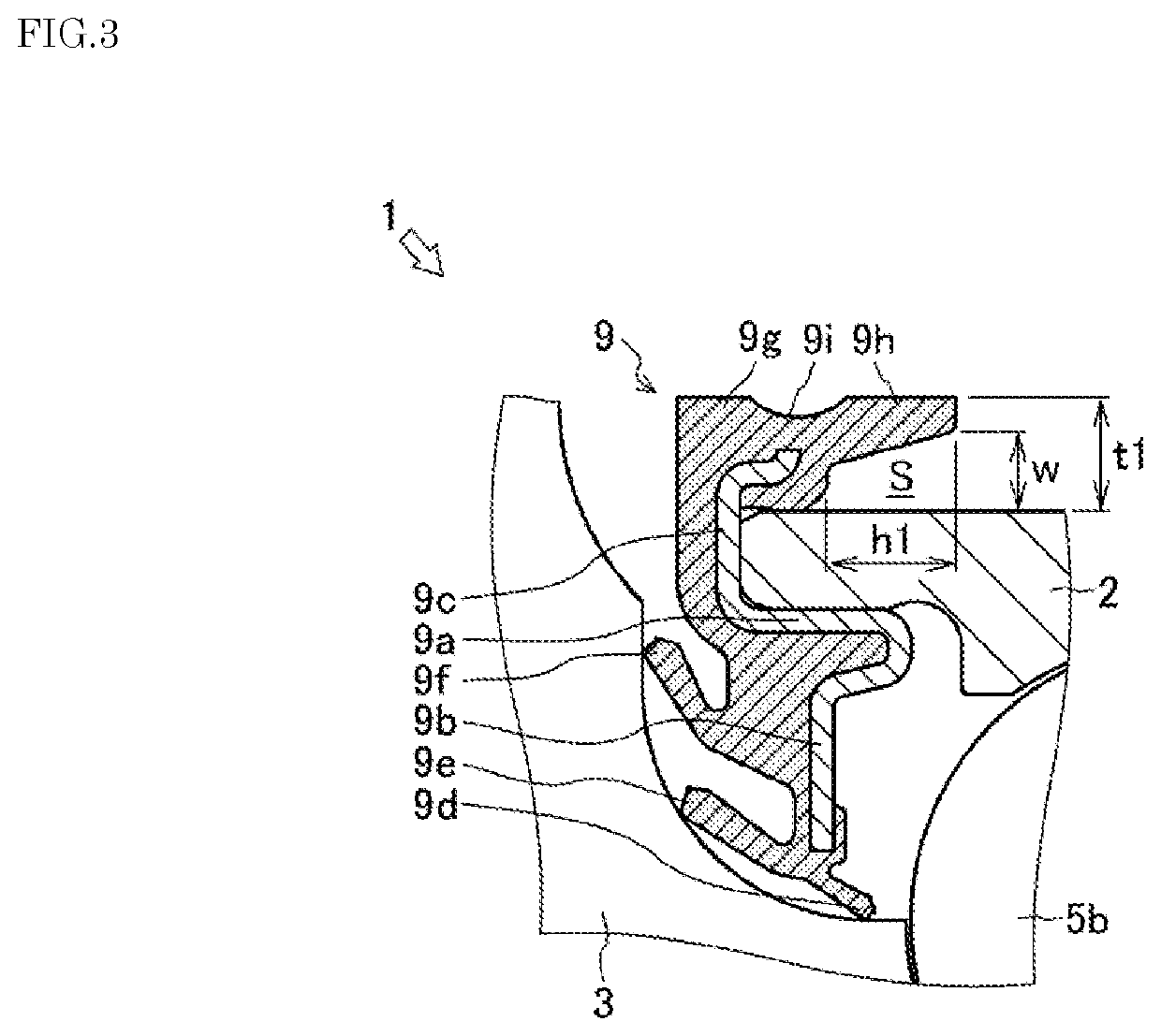
The present invention provides a structure for a dam to prevent muddy water or other such substances from leaking or overflowing in a space between the outer surface of an outer member and the eaves section on the outer member. The dam section is formed on the flange section of the core metal, and a lip portion is covered by the inner eaves section to prevent muddy water from entering it. Additionally, an annular groove is formed to allow muddy water to flow downward through it even if it overflows. These features increase the effectiveness of the dam in preventing muddy water from leaking or damaging the structure.

Problems solved by technology

The bearing device for a wheel suffers from a shorter bearing lifetime due to rust formed by a leak of grease from an outer ring that is an outer member or entry of muddy water or the like or damage to the rolling element or a race of the inner member.
However, in the bearing device for a wheel, an increase in the number of seal lips or an increase in tightening force of the seal lips results in an increase in friction torque.

Method used


Image

  • Bearing device for vehicle wheel
  • Bearing device for vehicle wheel
  • Bearing device for vehicle wheel

Examples


first embodiment

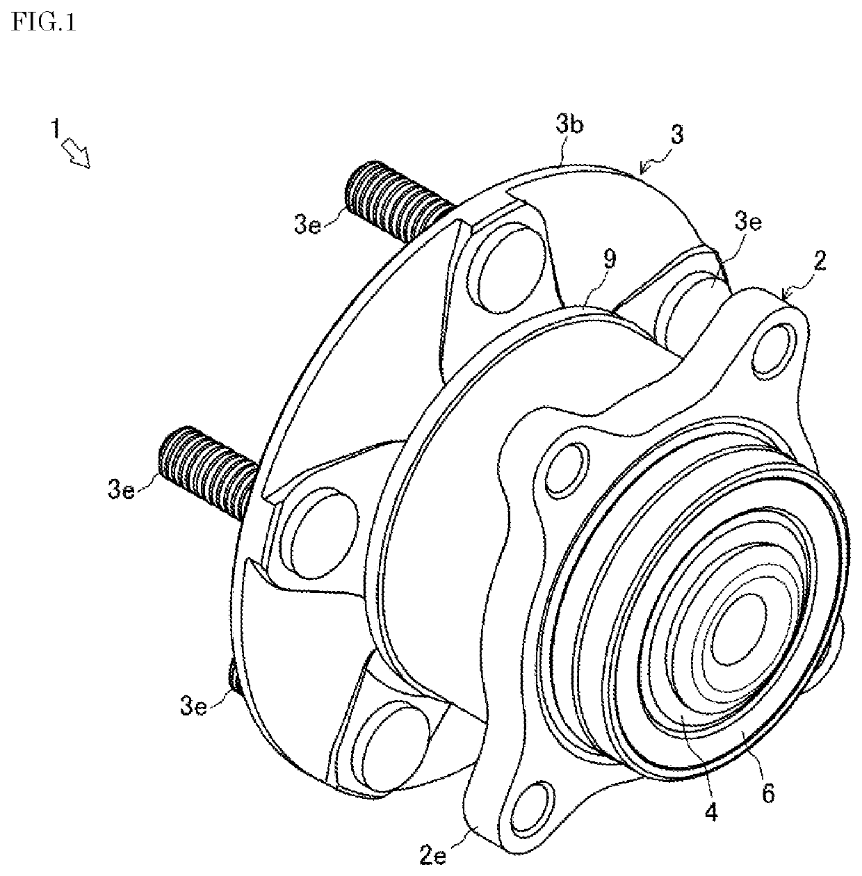
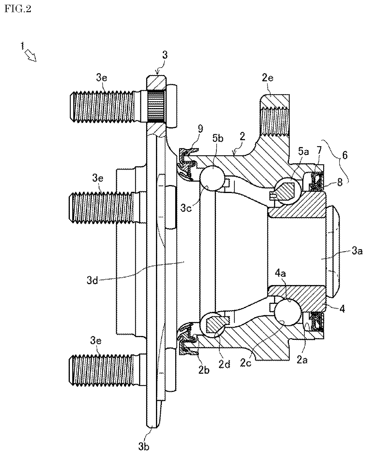
[0028]A description will be given below of a bearing device for a vehicle wheel 1 corresponding to a bearing device for a wheel according to the present invention with reference to FIGS. 1 to 3.

[0029]As shown in FIGS. 1 and 2, the bearing device for a vehicle wheel 1 supports a wheel rotatable on a suspension device of a vehicle such as an automobile. The bearing device for a vehicle wheel 1 includes an outer ring 2 that is an outer member, a hub ring 3 that is an inner member, an inner ring 4, two rows of inner-side balls 5a and outer-side balls 5b that are rolling rows, an inner-side seal member 6 that is a seal member, and an outer-side seal member 9 that is a seal member. Note that, herein, the inner side refers to a vehicle body side of the bearing device for a vehicle wheel 1 when installed on the vehicle body, and the outer side refers to a wheel side of the bearing device for a vehicle wheel 1 when installed on the vehicle body. An axial direction refers to a direction along...

second embodiment

[0052]Next, a description will be given of a bearing device for a wheel 10 corresponding to the bearing device for a wheel according to the present invention with reference to FIGS. 6A and 6B. Note that bearing devices for a wheel 102, 14, and 16 according to the following embodiments are each applied in place of the bearing device for a wheel 10 shown in FIGS. 1 to 5, and the names, figure numbers, and reference numerals used in the description given of the bearing device for a wheel 10 are used to denote the same components. That is, in the following embodiments, no detailed description will be given of the same points as the points of the embodiment already described, and a description will be mainly given of different points.

[0053]As shown in FIG. 6A, an outer-side seal member 11 of the bearing device for a wheel 10 closes the gap between the outer-side opening 2b of the outer ring 2 and the hub ring 3. The outer-side seal member 11 is formed of a plurality of seal lips and a co...

third embodiment

[0058]Next, a description will be given of a bearing device for a wheel 12 corresponding to the bearing device for a wheel 12 according to the present invention with reference to FIGS. 7A and 7B.

[0059]As shown in FIG. 7A, an outer-side seal member 13 of the bearing device for a wheel 12 closes the gap between the outer-side opening 2b of the outer ring 2 and the hub ring 3. The outer-side seal member 13 is formed of a plurality of seal lips and a core metal that is provided with the seal lips and has an approximately cylindrical shape. On the core metal, a circular cylinder section 13a, a circular plate section 13b, and a flange section 13c are formed. A radial lip 13d, an inner axial lip 13e, and an outer axial lip 13f each formed in an annular shape are integrally provided on a plate surface of the circular plate section 13b of the core metal by, for example, vulcanization bonding. A dam section 13g, an outer member-side eaves section 13h, and an inner member-side eaves section 13...


PUM


Abstract

A bearing device for a wheel is disclosed. The bearing device includes: an outer ring; a hub ring having at least one inner ring, and double rows of inner rolling surfaces on an outer periphery of the hub ring; double rows of balls in between respective rolling surfaces of the outer ring and the hub ring; and an outer seal member. The bearing device further includes: core metal having a circular cylinder section and a circular plate section at an opening of the outer ring; and a lip having an elastic body and being positioned on the circular plate section. An annular dam section having an elastic body and protruding further radially outward than an outer peripheral surface of the outer ring extends from the circular plate section, and an outer member-side eaves section has a circular cylindrical shape and protrudes axially so as to surround the outer ring.

Description

BACKGROUND OF THE INVENTION1. Technical Field[0001]The present invention relates to a bearing device for a wheel.2. Description of the Related Art[0002]A bearing device for a wheel that supports a wheel rotatable on a suspension device of, for example, an automobile is conventionally known. In the bearing device for a wheel, a hub ring that is an inner member connected to the wheel is rotatably supported with a rolling element. The bearing device for a wheel suffers from a shorter bearing lifetime due to rust formed by a leak of grease from an outer ring that is an outer member or entry of muddy water or the like or damage to the rolling element or a race of the inner member. To address such a problem, the bearing device for a wheel is provided with a seal member that prevents sealed-in grease from leaking out from a gap between the outer member and the inner member and also prevents muddy water or the like from entering from the outside.[0003]As such a bearing device for a wheel, t...

Claims


Application Information

Patent Timeline
Patent Type & Authority Patents(United States)
IPC IPC(8): F16C33/78F16C19/38B60B27/00
CPCF16C33/7823B60B27/0073F16C19/38F16C2326/02B60B2900/5112B60B27/001B60B2900/211B60B2900/5114F16C19/186F16C33/783
Inventor KOIZUMI, SOUTA
Owner NTN CORP
Learn More