Emergency lighting converter

a technology of emergency lighting and converter, which is applied in the direction of emergency power supply arrangements, electrical appliances, electric vehicles, etc., can solve the problems of high timing requirements and exceed the capabilities of cost effective microprocessors, and achieve the effect of fast and efficient control algorithms

Active Publication Date: 2021-04-20
TRIDONIC
View PDF10 Cites 0 Cited by
  • Summary
  • Abstract
  • Description
  • Claims
  • Application Information

AI Technical Summary

Benefits of technology

[0006]Furthermore, using the coupled inductor boost topology for the driving circuit enables to drive lighting means such as LEDs of an LED module as load to the converter with a high voltage rating at a low duty cycle contrary to using the conventional boost converter topology. The switching frequencies of the coupled inductor boost converter are accordingly higher when compared to the conventional boost converter topology. This results in a conductor (“boost choke”) of lower dimensions and smaller associated circuit elements which provides further advantages in space and cost.
[0014]Using an analogue comparator available in microcontroller circuits in combination with using information on a polarity reversion of the inductor current acquired by sensing a current over the switch, enables to implement a fast and efficient control algorithm suitable for implementation on a microcontroller circuit on one hand and capable to control the drive circuit at high switching frequencies on the other hand.

Problems solved by technology

Due to the high switching frequencies employed in contemporary SMPs, the requirements with respect to timing are high, exceed the capabilities of cost effective microprocessors and usually met by dedicated application specified circuits employed as LED driver ICs for controlling the LED driver.

Method used


Image

  • Emergency lighting converter
  • Emergency lighting converter
  • Emergency lighting converter

Examples


Embodiment Construction

[0025]In the figures, same numerals denote the same or corresponding elements. For sake of conciseness, the description of the figures omits repeating the description of same reference signs for different figures.

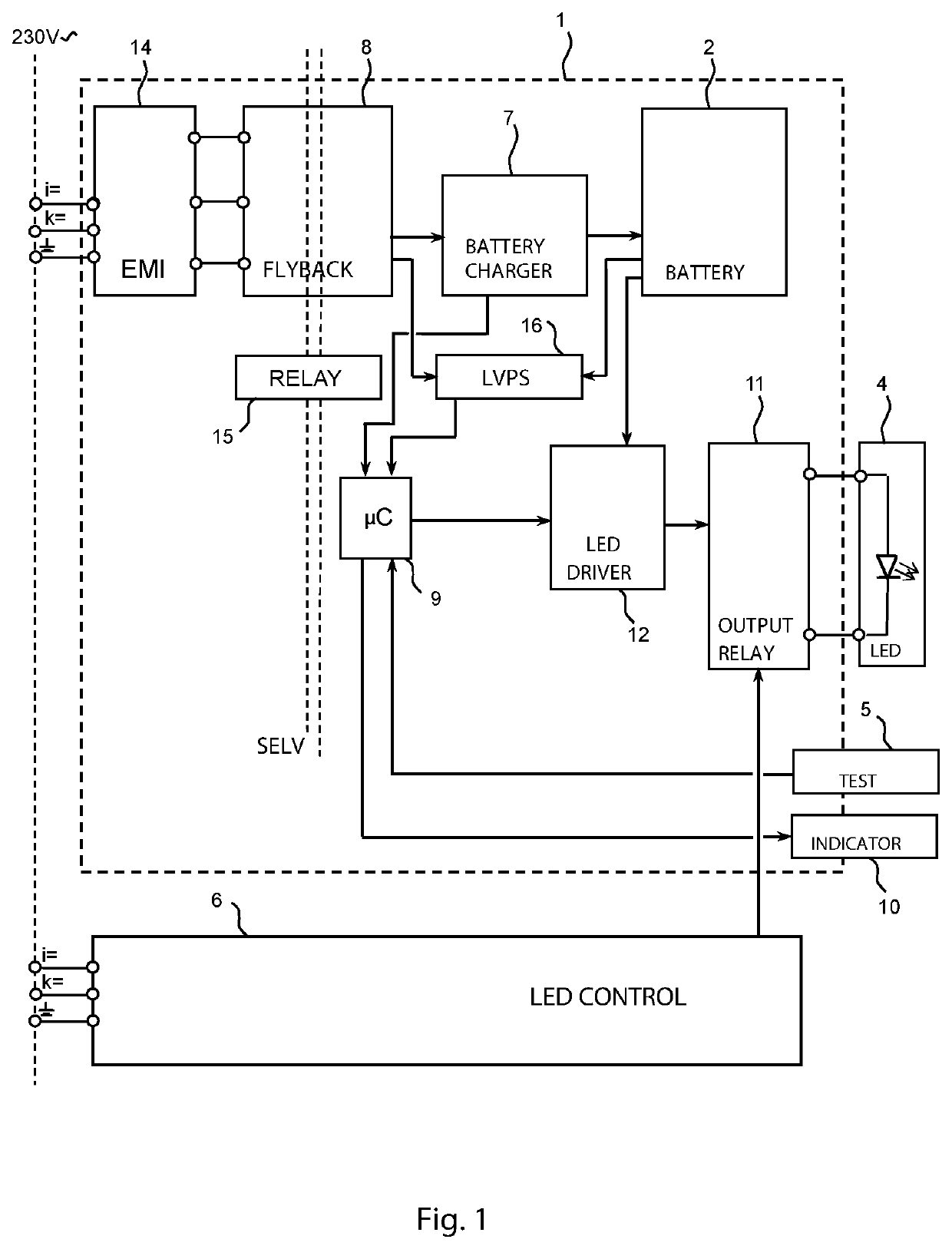
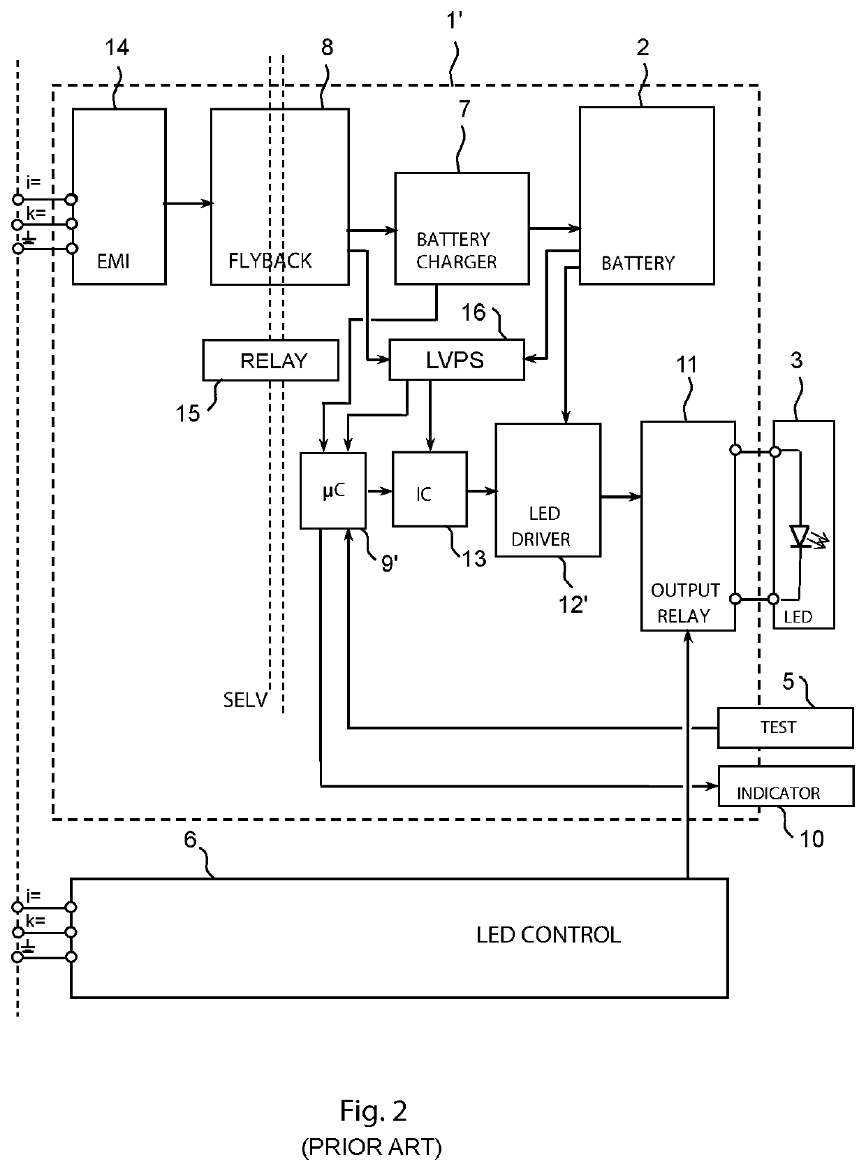
[0026]Before presenting an embodiment of the invention based on FIG. 1, a general overview of major elements of a known emergency converter device for driving an emergency light from an energy storage device, for example a battery and in particular a rechargeable battery, is provided based on FIG. 2.

[0027]A usual way to provide emergency lighting uses battery backed emergency converter devices 1′ that are installed within or adjacent to existing lighting fixtures. Upon sensing mains supply failure, the emergency converter device 1′ switches into an emergency mode turning the existing lighting into emergency lighting in order to meet the requirements of an emergency lighting without the need of wiring separate emergency lighting circuits or additional wall mounts.

[0028]The d...


PUM


Abstract

An emergency converter according to the invention is used in lighting applications for operation from an energy storage device in case of mains failure. The converter device comprises a charger circuit configured to charge the energy storage device and a microcontroller circuit configured to control the charger circuit. The driver circuit is preferably implemented in a coupled inductor boost circuit topology. The microcontroller circuit is further configured to control the switch based on a zero crossing of a measured inductor current.

Description

CROSS REFERENCE TO RELATED APPLICATIONS[0001]The present application is the U.S. national stage application of international application PCT / EP2018 / 060987 filed Apr. 27, 2018, which international application was published on Nov. 29, 2018 as International Publication WO 2018 / 215171 A1. The international application claims priority to Great Britain Patent Application 1708460.9 filed May 22, 2017.FIELD OF THE INVENTION[0002]The invention relates to the field of switched mode power supplies, in particular to converters adapted to operate from energy storages and used in lighting applications such as emergency converters. In particular, the invention proposes a fast closed loop system in a converter using a microcontroller.BACKGROUND OF THE INVENTION[0003]Emergency lighting for a building relies on battery backed lighting devices that switch on automatically in an emergency mode of operation, when a power outage is detected. An emergency lighting system includes an energy storage device...

Claims


Application Information

Patent Timeline
Patent Type & Authority Patents(United States)
IPC IPC(8): H02J7/00H02J9/02H02J9/06H05B45/37H05B44/00
CPCH02J9/02H02J7/00H02J9/061H05B45/37H05B45/38H05B45/385H02J9/06H05B44/00
Inventor MAKWANA, DEEPAKSHUKLA, JAGJITPATI
Owner TRIDONIC
Why Eureka
Try Eureka