Rotary drill head for coiled tubing drilling apparatus

a drilling apparatus and rotary drill head technology, which is applied in the direction of drilling rods, drilling pipes, rotary drilling, etc., can solve the problems of significant time and energy consumed in adding and removing pipe sections, and bring operational limitations, so as to increase the operational life of the tubing, reduce the stress on the tubing, and minimize the effect of further stress

Active Publication Date: 2021-05-04
MINEX CRC LTD
View PDF689 Cites 2 Cited by
  • Summary
  • Abstract
  • Description
  • Claims
  • Application Information

AI Technical Summary

Benefits of technology

[0015]During further description of the present invention, two modes of operation will be referred to. The first mode will be a coiled tubing drilling mode, where the coiled tubing is inserted down the borehole and fluid passed down the tubing powers the bottom hole assembly. The second mode will be a conventional rotating drill string mode where the coiled tubing connects to the top swivel of the rotary drill head and moves no further than that, while pipe sections are connected to the bottom spindle of the rotary drill head forming a rotating drill string for the bottom hole assembly. The use of the present invention allows for a relatively simple transition between the two operation modes, with relatively simple apparatus.
[0040]The y direction movement is movement of the reel along its own longitudinal axis, again so as to maintain the pay-off point of the tubing adjacent to the tubing abutment as the tubing uncoils from the reel. In this respect, it will be appreciated that the pay-off point of the tubing will move along the longitudinal axis of the reel as the reel rotates about its longitudinal axis and as the tubing uncoils. With the reel being adapted to provide for continual adjustability of the reel along its longitudinal axis, the reel can be moved in the y direction in response to the pay-off point moving in the y-direction, thus keeping the pay-off point adjacent to the tubing abutment as required, and also keeping the tubing at that point in engagement with the tubing abutment to apply the requisite opposite bend thereto.

Problems solved by technology

A significant amount of time and energy (and thus cost) are consumed in adding and removing these pipe sections to assemble and disassemble drill strings during drilling.
The terms are not, however, intended to bring operational limitations, or a requirement for parts of the apparatus to be perfectly horizontal or perfectly vertical.

Method used


Image

  • Rotary drill head for coiled tubing drilling apparatus
  • Rotary drill head for coiled tubing drilling apparatus
  • Rotary drill head for coiled tubing drilling apparatus

Examples


Embodiment Construction

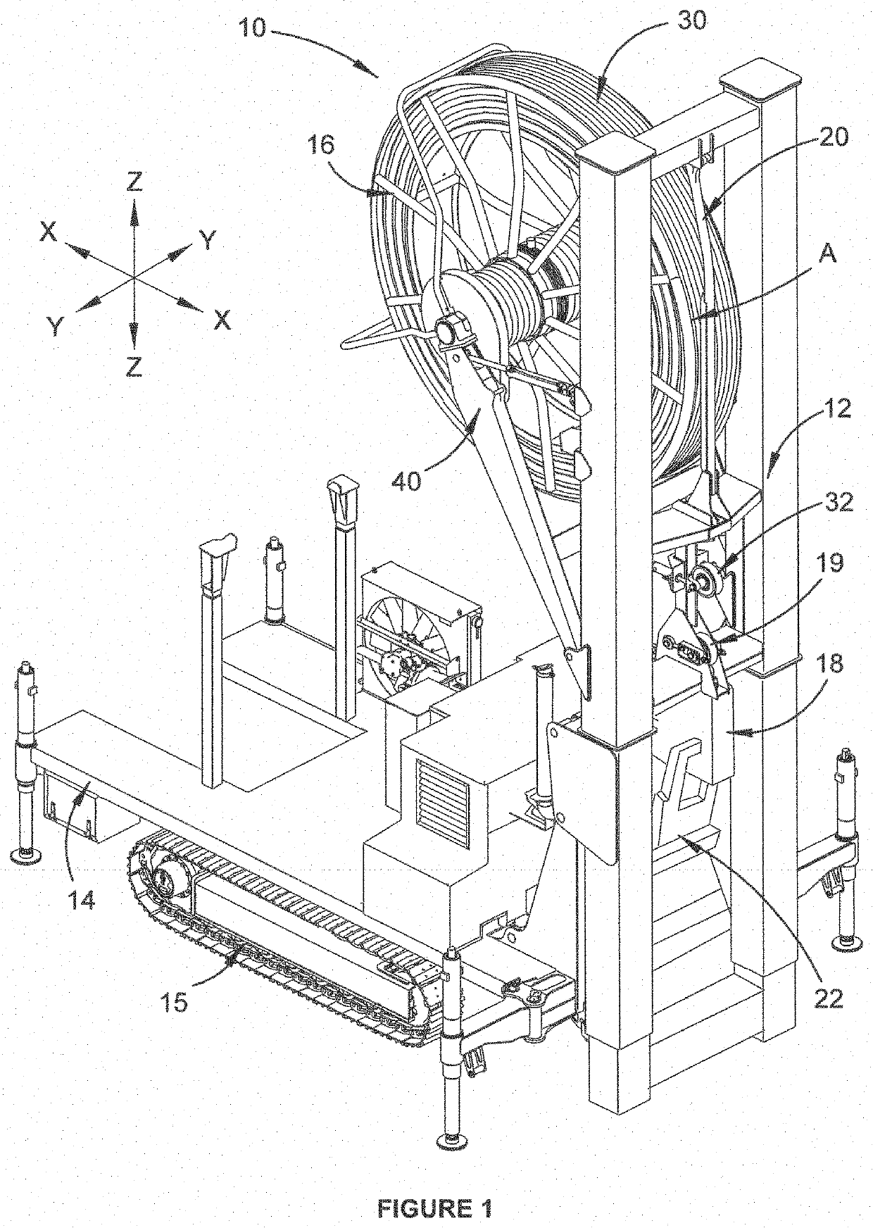
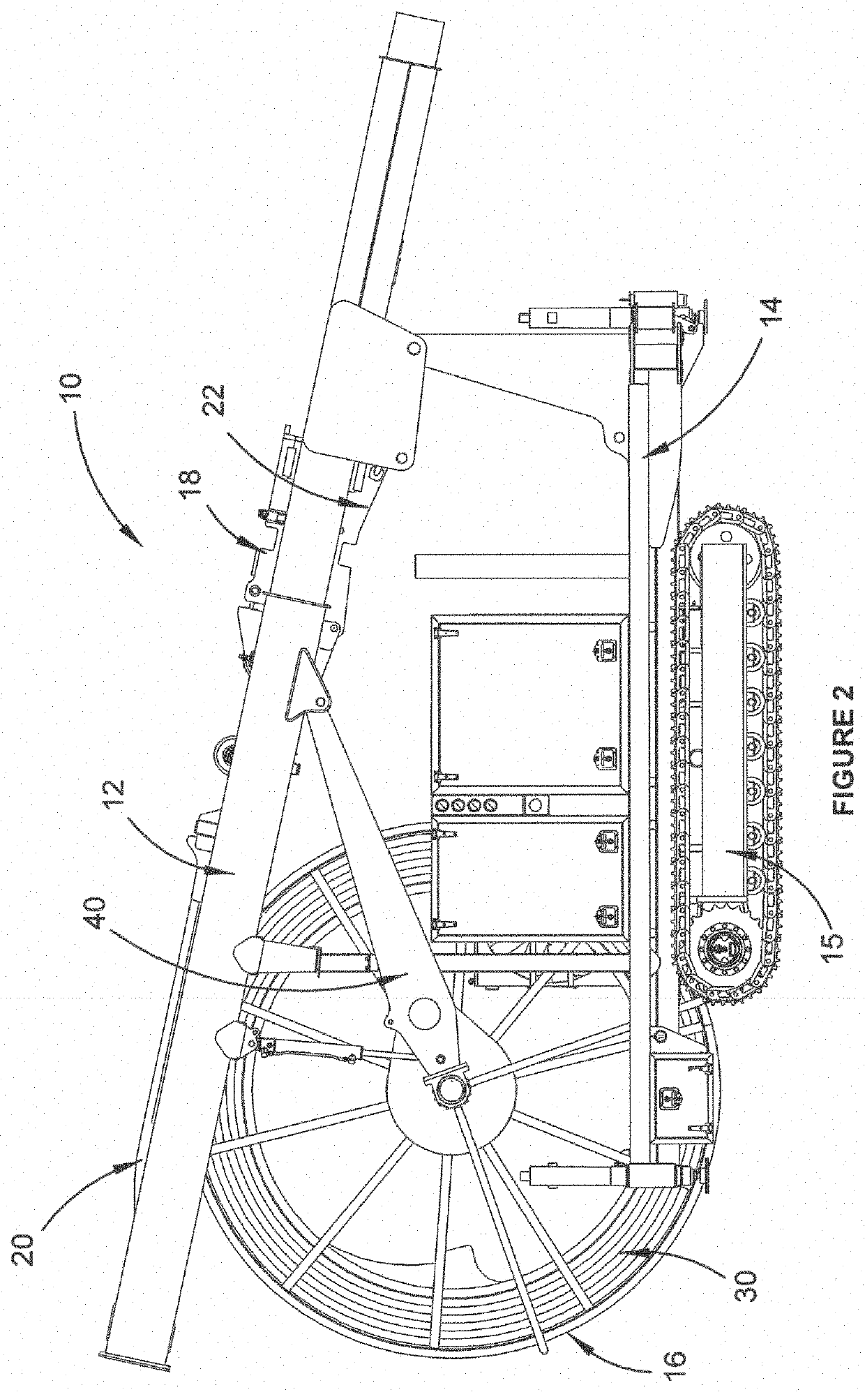
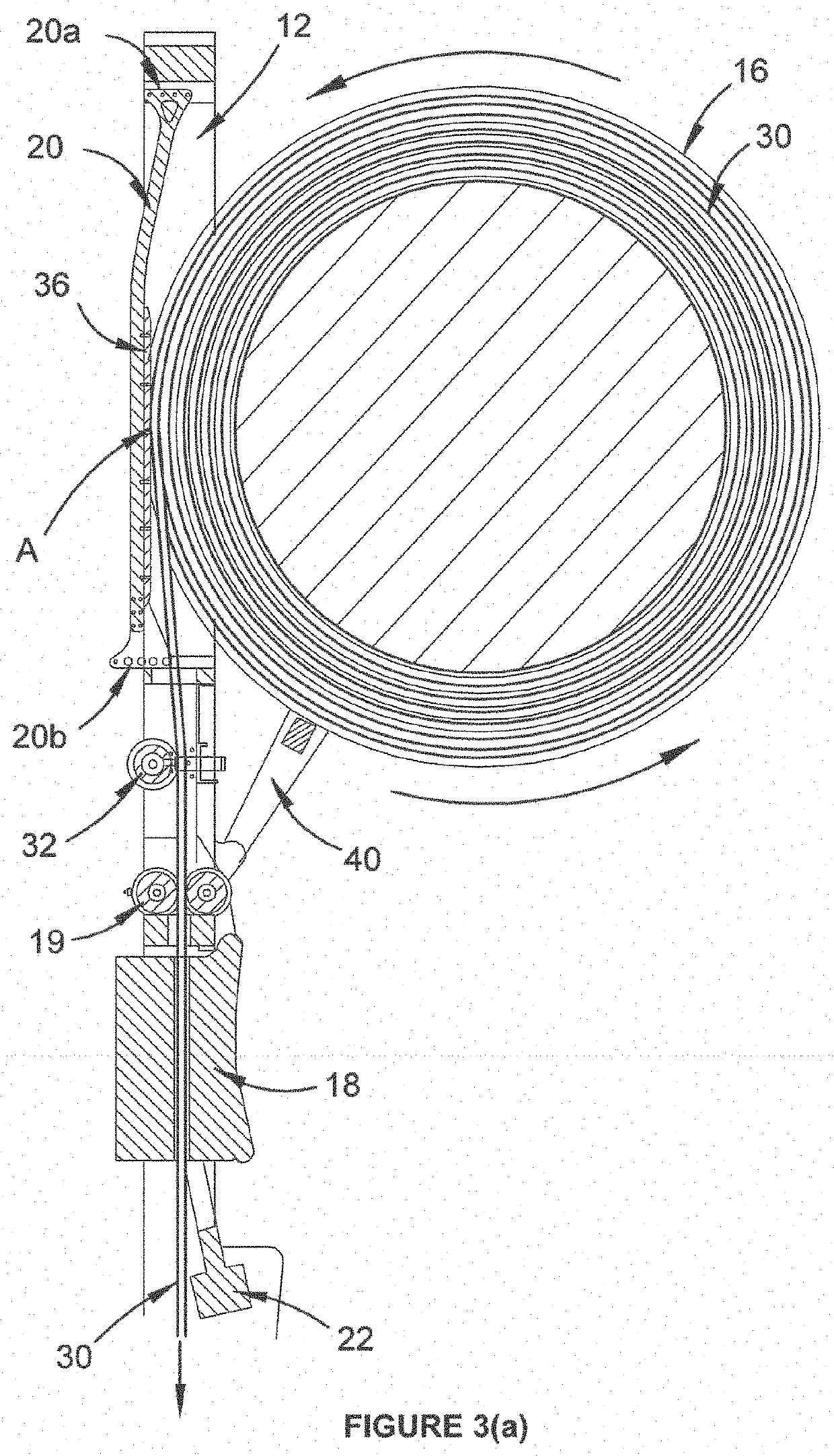
[0050]Illustrated in FIG. 1 is a mobile, coiled tubing drilling apparatus 10 in its upright drilling position, while FIG. 2 shows the same apparatus 10 in its lowered transport position. The apparatus 10 generally includes a mast 12 mounted on a mobile platform 14 in a manner such that the mast is not rotatable about a vertical axis when in its upright drilling position. The apparatus also includes a coiled tubing reel 16, an injector 18 (with injector guide rollers 19) and a tubing control system in the form of an elongate tubing abutment 20. As will be better understood from the following description, point A in FIG. 1 is a point on the reel and is the general location of both a tubing pay-off point and a tubing take-up point (referred to later as A′).

[0051]The vertical axis mentioned above is designated in FIG. 1 as the z axis in the identified x-y-z coordinate system, with the x axis (or x direction) being the direction of movement for the tubing pay-off point A (and thus also t...


PUM


Abstract

A mobile, coiled tubing drilling apparatus with a rotary drill head, includes a non-rotating mast on a mobile platform. The mast has mounted thereon an injector below a coiled tubing reel. The injector defines an operational axis for the coiled tubing. The rotary drill head is pivotally mounted on the injector so as to be movable between a retracted position away from the operational axis and an operating position in line with the operational axis. The rotary drill head includes a top swivel for non-rotating connection to the coiled tubing and a bottom spindle for rotating connection to a pipe section. The top swivel and the bottom spindle provide fluid communication between connected coiled tubing and connected pipe section during operation.

Description

RELATED APPLICATION[0001]This is the United States national phase of International Patent Application No. PCT / AU2017 / 051098, filed Oct. 11, 2017, which claims the priority benefit of Australian provisional patent application 2017900143 filed on 18 Jan. 2017 and International patent application PCT / AU2017 / 050508 filed on 30 May 2017. The entire contents of each of the foregoing are expressly incorporated herein by reference.TECHNICAL FIELD[0002]The present invention relates to a rotary drill head for a coiled tubing drilling apparatus, primarily for use in mineral exploration, the drilling apparatus being of the type where the coiled tubing is not required to rotate about its longitudinal axis in order for the drilling apparatus to operate.BACKGROUND OF INVENTION[0003]Mineral exploration has historically used rotating drill strings (being a series of attached, rigid, pipe sections) with drill bits attached at one end to drill subterranean holes in an effort to locate valuable mineral...

Claims


Application Information

Patent Timeline
Patent Type & Authority Patents(United States)
IPC IPC(8): E21B19/08E21B3/04B65H75/42B65H75/44E21B7/02E21B19/24E21B19/22E21B3/02E21B15/00
CPCE21B19/08B65H75/425B65H75/4405E21B3/02E21B3/045E21B7/02E21B7/021E21B7/023E21B15/00E21B19/22E21B19/24B65H2701/33
Inventor SØE, SØREN PHAMFOX, SHANE LEE
Owner MINEX CRC LTD
Why Eureka
Try Eureka