Control apparatus, optical apparatus, and control method for optical apparatus

a technology of control apparatus and control method, which is applied in the direction of printers, instruments, cameras, etc., can solve the problems of difficult intuitive focusing by users, error in the actual drive amount of optical elements, etc., and achieve the effect of improving the driving accuracy of optical elements

Active Publication Date: 2021-05-11
CANON KK
View PDF23 Cites 1 Cited by
  • Summary
  • Abstract
  • Description
  • Claims
  • Application Information

AI Technical Summary

Benefits of technology

[0005]The present invention provides a control apparatus, an optical apparatus, and a control method for an optical apparatus, each of which can improve a driving accuracy of an optical element for its rotational position with an endlessly rotatable electronic ring.

Problems solved by technology

Using the electronic ring is likely to cause an error in an actual drive amount of the optical element in comparison with the rotational operational amount of the electronic ring, due to an intervention of an electrical control between the manual operation and driving of the optical element.
For example, even when the electronic ring for the focusing operation is once operated and returned to the pre-operation rotational position, the position of the focus lens does not return to the pre-operation position and intuitive focusing by the user becomes difficult.

Method used


Image

  • Control apparatus, optical apparatus, and control method for optical apparatus
  • Control apparatus, optical apparatus, and control method for optical apparatus
  • Control apparatus, optical apparatus, and control method for optical apparatus

Examples


first embodiment

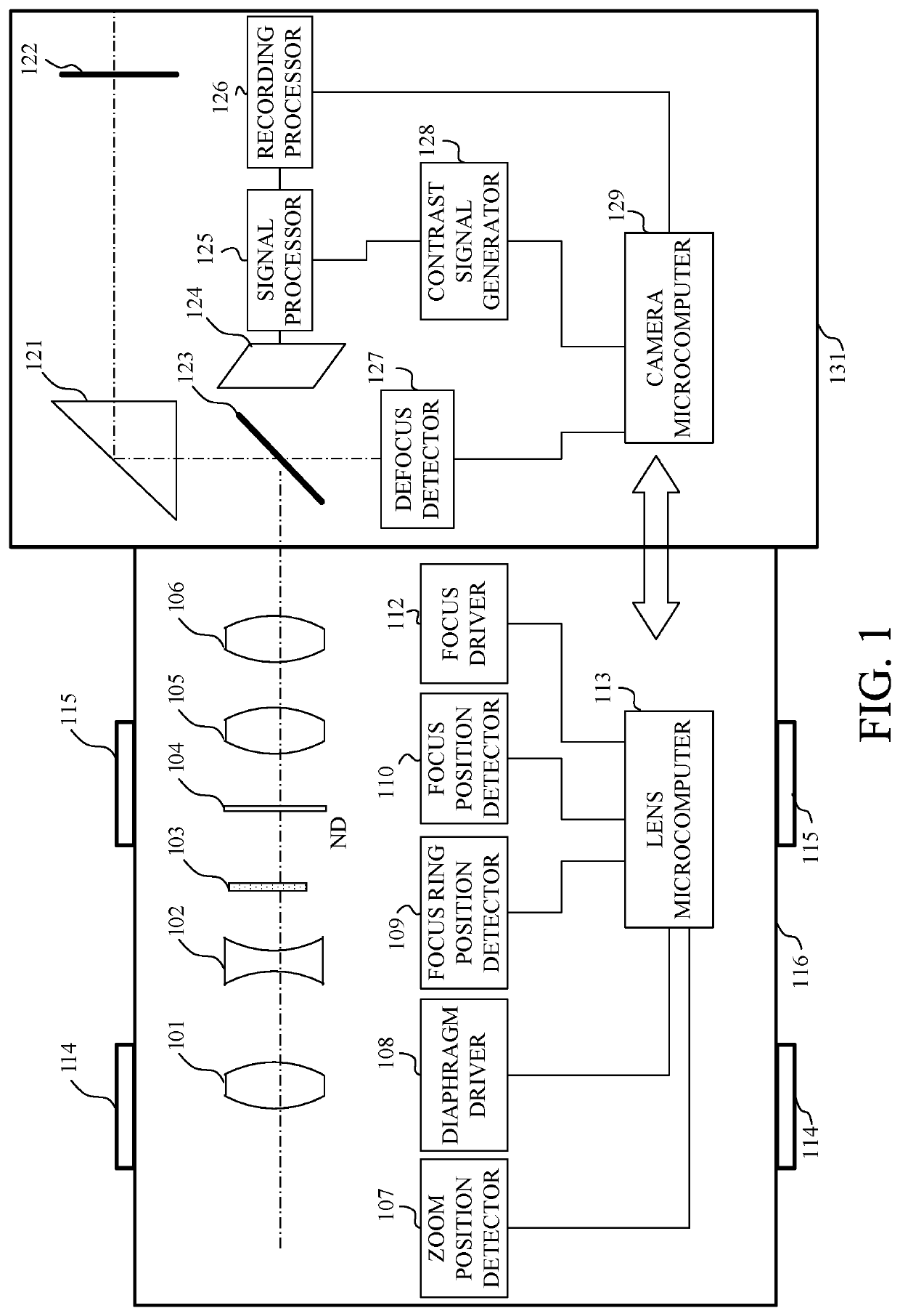
[0017]FIG. 1 illustrates a configuration of a camera system that includes an interchangeable lens 116 as an optical apparatus according to a first embodiment of the present invention, and a camera body 131 to which the interchangeable lens 116 is detachably attached.

[0018]Light from an unillustrated object enters an imaging optical system in the interchangeable lens 116. The imaging optical system includes a first lens 101, a zoom lens 102, a diaphragm (aperture stop) 103, an ND filter 104, a focus lens 105 as an optical element, and a fourth lens 106. The zoom lens 102 is movable in the optical axis direction for zooming. The focus lens 105 is movable in the optical axis direction in focusing. The diaphragm 103 controls a light amount by changing an aperture diameter. The ND filter 104 attenuates the light amount.

[0019]The light having passed through the imaging optical system is reflected by a main mirror 123 in the camera body 131, is guided to a pentagonal prism 121, passes thro...

second embodiment

[0063]The first embodiment discusses updating the ring and focus reference positions when the operation of the focusing operation ring 115 starts. However, when the operational velocity of the focusing operation ring 115 is low and the ring position gently changes, a transition (operation start) from the unoperated state to the operated state of the focusing operation ring 115 may be incorrectly determined during the operation. This incorrect determination would accordingly update the ring reference position and the focus reference position. In other words, the ring reference position and the focus reference position are updated while the focusing operation ring 115 is being operated or driven, and the correspondence relationship between the updated ring reference position and the updated focus reference position may shift from the original correspondence relationship when the operation starts. Accordingly, when the focusing operation ring 115 is operated at a low speed, it is neces...

third embodiment

[0065]When the operational direction of the focusing operation ring 115 is reversed, the focusing operation ring 115 stops rotating and starts rotating at the moment of the reversal, so that the operation start of the focusing operation ring 115 is determined and the ring reference position and the focus reference position are updated. If the operation of the focusing operation ring 115 is suddenly reversed, the focus lens 105 cannot be driven in time and the ring reference position and the focus reference position may be updated while the focus lens 105 is being driven. As a result, the correspondence relationship between the updated ring reference position and the focus reference position shifts from the original correspondence relationship. It is thus necessary to prevent the ring reference position and the focus reference position from being updated in the sudden reverse operation of the focusing operation ring 115.

[0066]Hence, a change amount (decrease amount) in the operationa...


PUM


Abstract

A control apparatus is used for an optical apparatus that includes a movable optical element, an operation ring that is endlessly rotatable, and a driver configured to drive the optical element. The control apparatus includes an operation start detector configured to detect a start of an operation of the operation ring, and a drive controller configured to control the driver. The drive controller sets a rotational position of the operation ring and the position of the optical element to a ring reference position and an optical element reference position respectively when the start of the operation of the operation ring is detected. The drive controller controls the driver in accordance with a drive amount of the optical element calculated with an operational amount of the operation ring from the ring reference position, and the optical element reference position.

Description

BACKGROUND OF THE INVENTIONField of the Invention[0001]The present invention relates to a control over driving of an optical element in accordance with an operation of a manual operation ring.Description of the Related Art[0002]One of the above optical apparatuses detects a rotational operational amount of an electronic ring as a manual operation ring through a sensor and drives an optical element, such as a focus lens, by a drive amount converted from the rotational operational amount. Using the electronic ring is likely to cause an error in an actual drive amount of the optical element in comparison with the rotational operational amount of the electronic ring, due to an intervention of an electrical control between the manual operation and driving of the optical element. For example, even when the electronic ring for the focusing operation is once operated and returned to the pre-operation rotational position, the position of the focus lens does not return to the pre-operation po...

Claims


Application Information

Patent Timeline
Patent Type & Authority Patents(United States)
IPC IPC(8): G02B7/09G03B5/00G03B13/36G03B13/34H04N5/232G02B7/08G03B17/14
CPCG02B7/09G03B5/00G03B13/34G03B13/36H04N5/232G02B7/08G03B17/14G03B2205/0046H04N23/55H04N23/67H04N23/60
Inventor KAKIMOTO, TAKESHI
Owner CANON KK
Why Eureka
Try Eureka