System for fastening attachments to a substrate with an insulation layer

a technology of substrate and attachment, applied in the direction of heat-proofing, hinges, door/window fittings, etc., can solve the problems of unsightly insulation layer in the outer wall, more difficult to fasten heavy attachments, etc., and achieve the effect of simple means and better holding

Active Publication Date: 2021-05-18
EJOT BAUBEFESTIGUNGEN GMBH
View PDF13 Cites 1 Cited by
  • Summary
  • Abstract
  • Description
  • Claims
  • Application Information

AI Technical Summary

Benefits of technology

[0008]The fastening system according to the invention allows a long-term, beautiful and tight installation of an attachment with simple means. The mounting tool ensures that a predefined free space is formed around the anchor bolt in which the anchor bolt can move or deform in response to external forces without this having any effect on the insulation layer and / or a plaster layer applied to it. This is particularly the case because the mounting tool is removed again after the opening or free space has been formed. Until then, however, the mounting tool keeps the anchor bolt centered in the free space and thus ensures that, for example, if the anchor bolt is fixed with an adhesive, the anchor bolt cannot move during curing of the adhesive. This can be, for example, the setting process of a composite anchor mortar. The mounting tool and / or the anchor bolt preferably have means which ensure that the mounting tool and the anchor bolt are radially fixed during curing of the adhesive. According to the invention, the anchor bolt is aligned radially with the aid of the mounting tool, especially in the formed free space.
[0009]The sealing element can then be placed on the side of the insulation layer facing away from the substrate, which is also referred to as the outer side or outer surface of the insulation layer, and at the stop of the anchor bolt, thus sealing the opening from the outside. This means that if the anchor bolt moves due to external forces, the sealing element will not damage the insulation layer and will continue to seal the opening.
[0010]In a preferred embodiment, the anchor bolt consists of two elements, a plastic rod that forms the first area and a metal rod that forms the second area. Preferably, the metal rod has a thread with which it can be screwed into an opening in the plastic rod. But the person skilled in the art is aware that there are many possibilities to connect the two elements of the anchor bolt. A glass fibre reinforced plastic is preferably used for the plastic rod and stainless steel is preferably used for the metal bolt. In a preferred embodiment, the plastic rod has a profile on its outside, for example in the form of a thread. Such a thread can lead to a better hold in the substrate and / or in the insulation layer. In particular, the external thread can be used to create a bonding effect with the adhesive, for example the composite anchor mortar.
[0011]EPDM rubber is preferably used for the sealing element. The sealing element can have two sealing levels. One sealing level is formed between the sealing element and the outer side of the insulation layer, the other sealing level between the sealing element and the anchor bolt, in particular the second area of the anchor bolt. The sealing element preferably consists of a sealing member, for example a sealing ring made of EPDM rubber and a washer made of stainless steel. The sealing member is preferably configured in such a way that in case of a relative displacement of the anchor bolt under service load it compensates, due to its configuration, this relative displacement without loss of the sealing function. The washer of the sealing element can preferably be configured in such a way that it can be used as a stop and / or as a support surface for the attachment.

Problems solved by technology

This, however, makes it more difficult to fasten heavy attachments to the outer walls, as the fasteners for heavy attachments cannot be attached to the insulation layer itself, but only to the substrate behind or below it, so that the attachments are at a certain distance from the supporting substrate.
This causes the insulation layer around the fastener to widen, making the insulation layer in this area unsightly and allowing moisture to penetrate into the insulation layer.

Method used


Image

  • System for fastening attachments to a substrate with an insulation layer
  • System for fastening attachments to a substrate with an insulation layer

Examples


Embodiment Construction

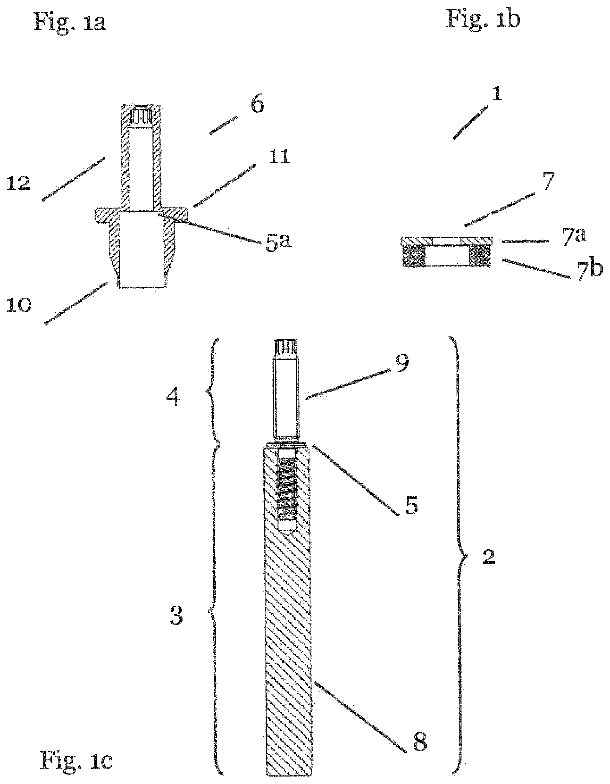
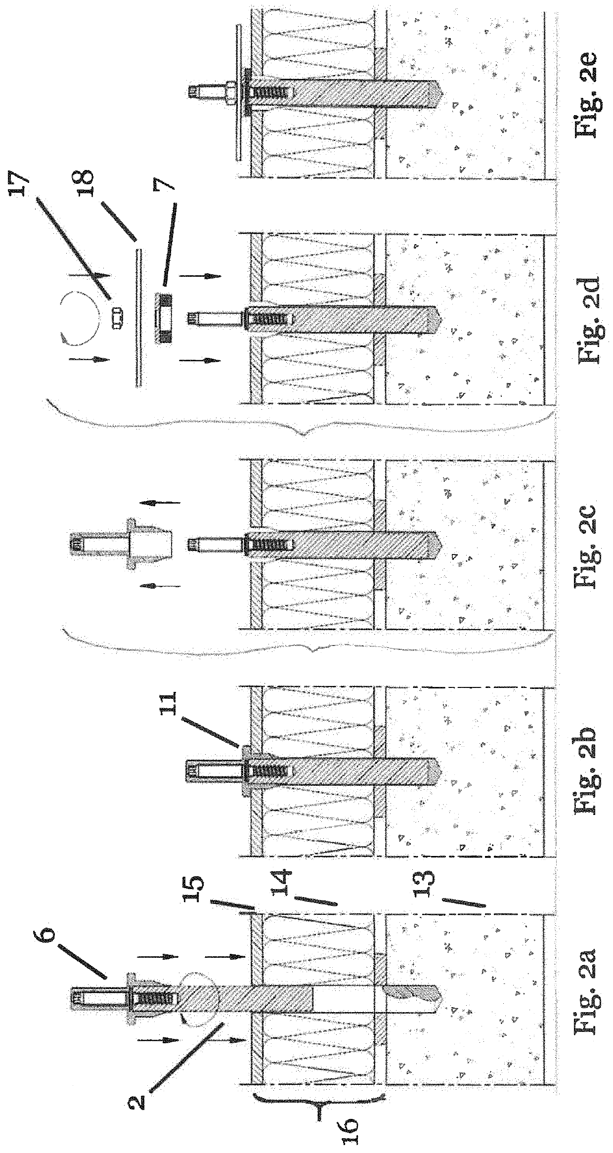
[0022]FIG. 1 shows an exemplary embodiment of the fastening system 1 according to the invention. This fastening system 1 has at least three elements, an anchor bolt 2, a mounting tool 6 and a sealing element 7.

[0023]According to the invention, the anchor bolt 2 has two areas. A first area 3 provides the anchoring in a substrate. In the embodiment shown in FIG. 1, this first area 3 is formed by a plastic rod 8. This plastic rod 8 is pushed into a borehole in which, for example, an adhesive is located and with the adhesive the plastic rod 8 and thus the entire fastening system 1 is anchored in the borehole. The anchor bolt 2 also has a second area 4 to which an attachment can be fastened. In the embodiment shown in FIG. 1, the second area 4 is formed by a metal bolt 9. In this embodiment, the metal bolt 9 has an external thread, to which the attachment can be fastened with the aid of a nut, for example. In addition, the external thread can also be used to attach the sealing element 7 ...


PUM

PropertyMeasurementUnit
distanceaaaaaaaaaa
areaaaaaaaaaaa
flexibleaaaaaaaaaa

Abstract

Fastening system (1) for fastening an attachment (18) to a substrate (13) with an insulation layer (16), the fastening system (1) comprising an anchor bolt (2), with a first area (3) for anchoring in the substrate (13), a second area (4) to which the attachment (18) can be fastened, and a stop (5), a mounting tool (6) to form an opening in the insulation layer (16), and a sealing element (7) adapted to be disposed at the stop (5) after the mounting tool (6) has been removed and to seal the opening in the insulation layer (16) as well as a corresponding method.

Description

FIELD OF THE INVENTION[0001]This invention relates a system for fastening attachments to a substrate with an insulation layer and a corresponding method.BACKGROUND OF THE INVENTION[0002]Insulation layers are applied to exterior walls to improve the insulation of houses. This, however, makes it more difficult to fasten heavy attachments to the outer walls, as the fasteners for heavy attachments cannot be attached to the insulation layer itself, but only to the substrate behind or below it, so that the attachments are at a certain distance from the supporting substrate. Such a fastening system is described in DE to 2008 004 753 A1.[0003]Attachments, such as canopies, have to withstand different loads. If there is snow on a canopy, it becomes heavier and therefore it is pushed downwards, while a gust of wind can push the canopy upwards. This causes the insulation layer around the fastener to widen, making the insulation layer in this area unsightly and allowing moisture to penetrate in...

Claims


Application Information

Patent Timeline
Patent Type & Authority Patents(United States)
IPC IPC(8): E04B1/76E05D5/02
CPCE04B1/7637E04B1/7633E05D2005/0292E05Y2800/674E05Y2800/676
Inventor DRATSCHMIDT, FRANKACHENBACH, RENESCHAEFER, WOLFGANG
Owner EJOT BAUBEFESTIGUNGEN GMBH
Why Eureka
Try Eureka