Supercharge Your Innovation With Domain-Expert AI Agents!

Synchronized multi-axis gyroscope

a multi-axis, synchronized technology, applied in the direction of speed measurement using gyroscopic effects, instruments, surveying and navigation, etc., can solve the problems of proof mass being prone to undesired oscillatory movement, and affecting the accuracy of gyroscopes

Active Publication Date: 2021-06-01
MURATA MFG CO LTD
View PDF40 Cites 0 Cited by
  • Summary
  • Abstract
  • Description
  • Claims
  • Application Information

AI Technical Summary

Benefits of technology

The present patent aims to provide a reliable and accurate multiaxis gyroscope with a simple structure. The idea is to synchronize the oscillation of two proof mass pairs with a ring-like body that connects them at a central symmetry point. The arrangement allows for flexible oscillation modes and prevents unwanted cophasal oscillation modes. The patent proposes using suitable suspensions and connections between the synchronization element and the surrounding proof mass to achieve desired anti-phase oscillation modes.

Problems solved by technology

Proof masses may be prone to undesired oscillatory movement when external vibrations or shocks act on the gyroscope.
Such external vibrations can cause disturbances in the angular rate measurement due to overloading of the transducers and / or amplifiers used for obtaining electrical signals.
This will pose a difficulty for the electronics.
Multiple sustaining and stabilizing circuits for the primary oscillation are needed, possible interference of the oscillation frequencies will cause undesired effects, and the area of the gyroscope will be relatively large, since up to 12 proof masses are needed for a robust three-axis operation.
A general problem in multiaxis gyroscopes with one oscillation frequency is that the desired primary and secondary oscillation modes of each proof mass comprise a multitude of different oscillations, some of which occur in the device plane and some out of the device plane.
Correspondingly, external vibrations in any direction may induce undesired cophasal oscillation.
Proof mass arrangements and suspension arrangements with sufficient mobility for the desired oscillation directions and phases, and sufficient rigidity for the undesired oscillation directions and phases, can be complicated.
Still it doesn't achieve robustness to external angular vibrations about any of the axes.

Method used


Image

  • Synchronized multi-axis gyroscope
  • Synchronized multi-axis gyroscope
  • Synchronized multi-axis gyroscope

Examples


Embodiment Construction

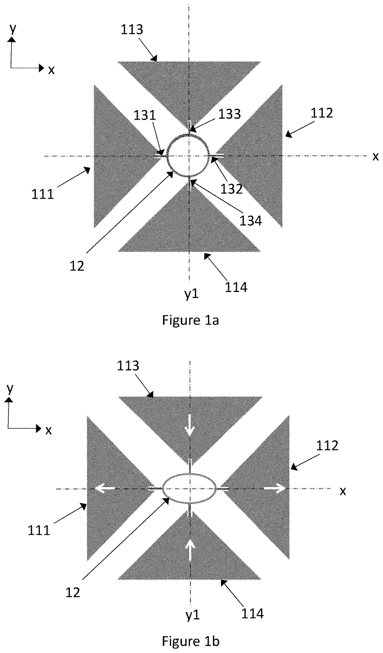
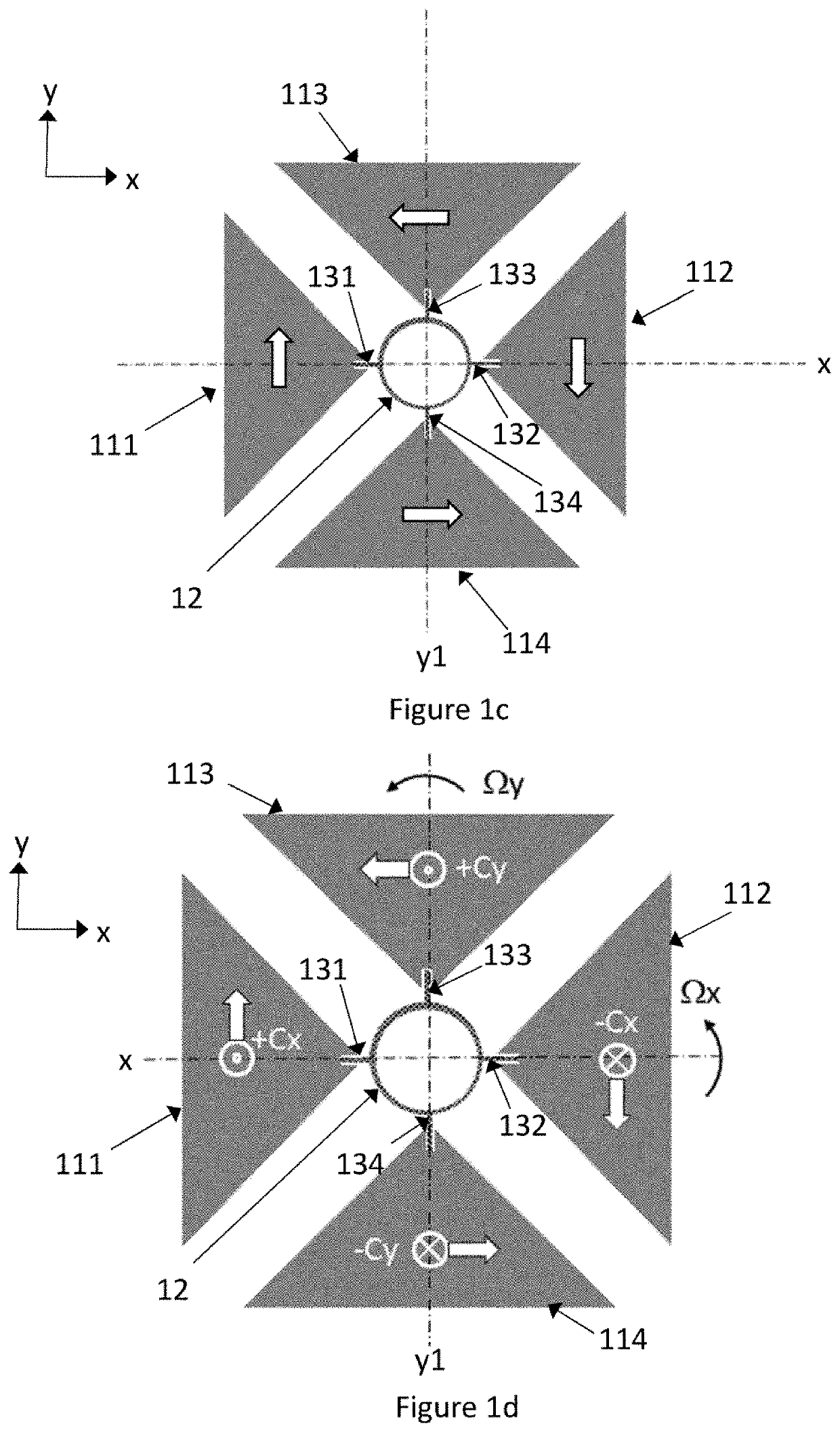
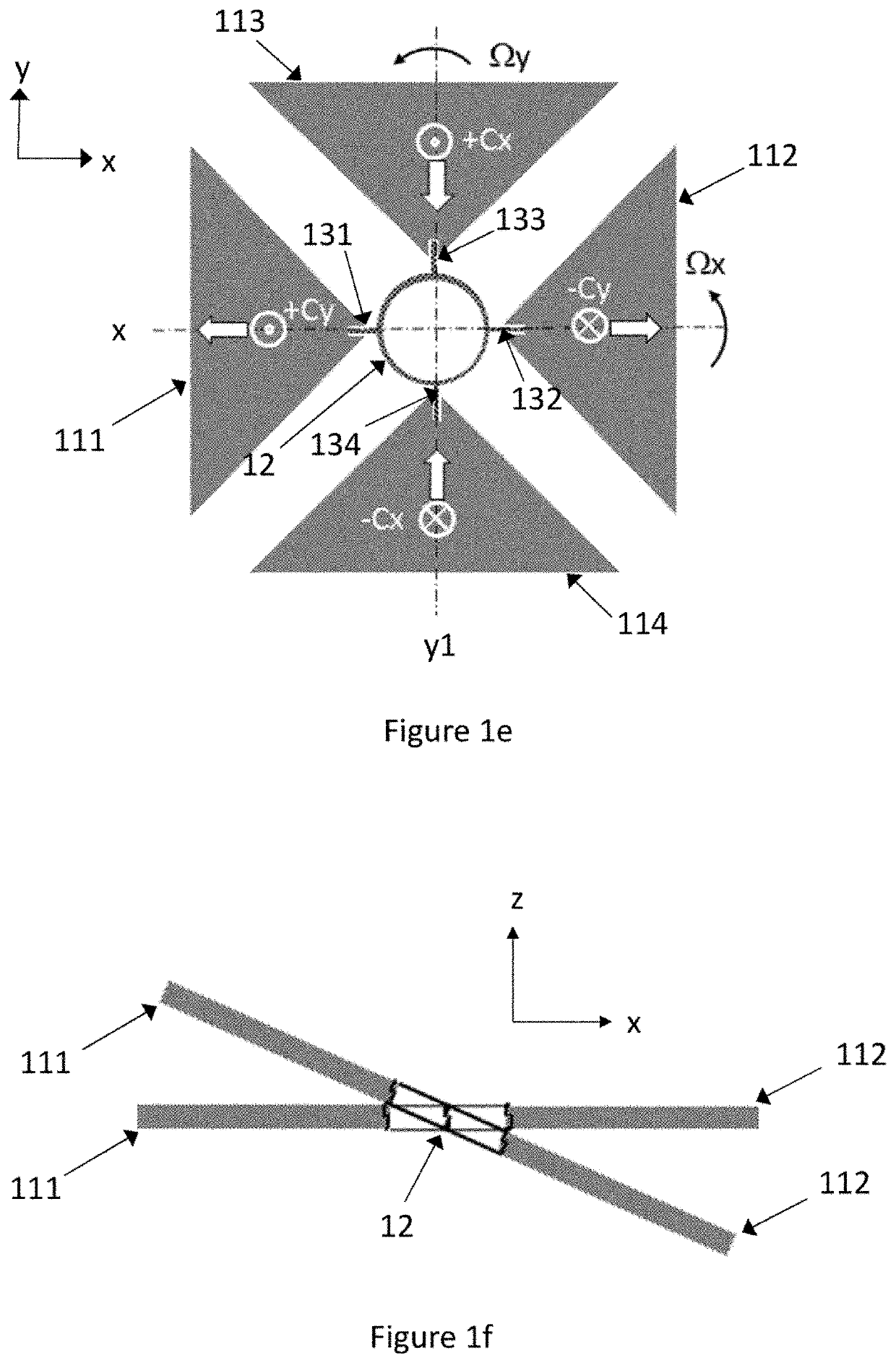
[0026]In this disclosure, expressions such as “orthogonal”, “parallel” and “symmetrical” are used to refer to orientations and distributions which should ideally be perfectly orthogonal / parallel / symmetrical. Nevertheless, slight deviations from perfect orthogonality, parallelity and symmetry are possible and to some extent unavoidable due to limitations in manufacturing accuracy. The person skilled in the art will understand that the same technical effect can usually be obtained even if the orientation or distribution deviates to some extent from orthogonality / parallelity / symmetry.

[0027]In this disclosure, the term “horizontal” refers to orientations that lie in the xy-plane illustrated in the figures. The horizontal xy-plane corresponds to the “device plane” defined by the surface of the substrate where the partly mobile elements of the gyroscope are formed. The partly mobile elements of the gyroscope typically lie in the device plane in their rest position, before they are moved b...


PUM


Abstract

The disclosure relates to a microelectromechanical gyroscope which comprises first and second proof masses which form a first proof mass pair and third and fourth proof masses which form a second proof mass pair. The oscillation of the first and second proof mass pairs is synchronized by a synchronization element which comprises a ringlike body and torsion bars which extend along the x-axis from the ringlike body to the first, second, third and fourth proof masses.

Description

FIELD OF THE DISCLOSURE[0001]This disclosure relates to microelectromechanical (MEMS) gyroscopes, and more particularly to multi-axis gyroscopes where proof masses may move in the device plane or out of the device plane in their primary and / or secondary oscillation modes. The present disclosure further concerns synchronization structures in such gyroscopes.BACKGROUND OF THE DISCLOSURE[0002]Microelectromechanical gyroscopes use the Coriolis effect to measure angular velocity. In oscillating MEMS gyroscopes, an object is driven into oscillating movement by an actuating drive force. This oscillation will be called “primary oscillation” or “drive oscillation” in this disclosure, and the oscillation mode will be labelled called the “primary oscillation mode”. It may also be labelled the primary resonance mode since mechanical resonance of a mass-suspension system is often used to increase the amplitude of the primary oscillation. In MEMS gyroscopes the drive oscillation can involve linea...

Claims


Application Information

Patent Timeline
Patent Type & Authority Patents(United States)
IPC IPC(8): G01C19/5712
CPCG01C19/5712G01C19/574
Inventor KUISMA, HEIKKIBLOMQVIST, ANSSIRYTKÖNEN, VILLE-PEKKA
Owner MURATA MFG CO LTD
Features
  • R&D
  • Intellectual Property
  • Life Sciences
  • Materials
  • Tech Scout
  • Unparalleled Data Quality
  • Higher Quality Content
  • 60% Fewer Hallucinations
Learn More