Gun tunnel sight

a tunnel sight and gun technology, applied in the direction of sighting devices, weapons, weapon components, etc., can solve the problems of insufficient alignment, more time and human error, complex and expensive existing mechanisms, etc., to enhance light concentration, and enhance the effect of light concentration

Active Publication Date: 2021-06-08
LEE SHANYAO
View PDF1 Cites 1 Cited by
  • Summary
  • Abstract
  • Description
  • Claims
  • Application Information

AI Technical Summary

Benefits of technology

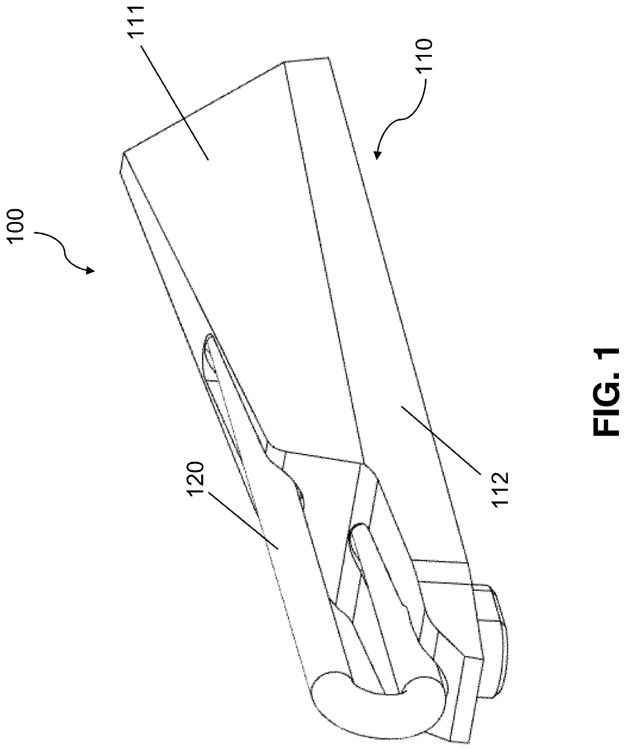
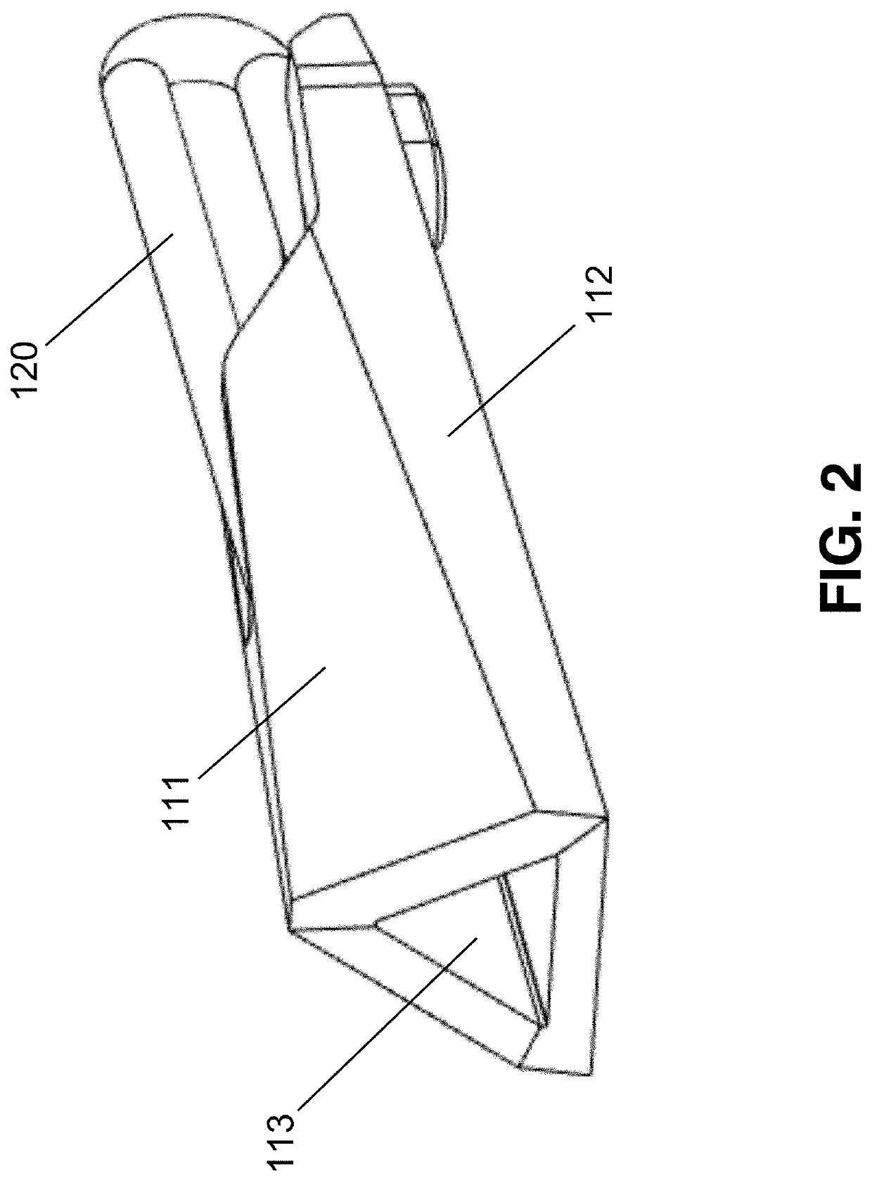
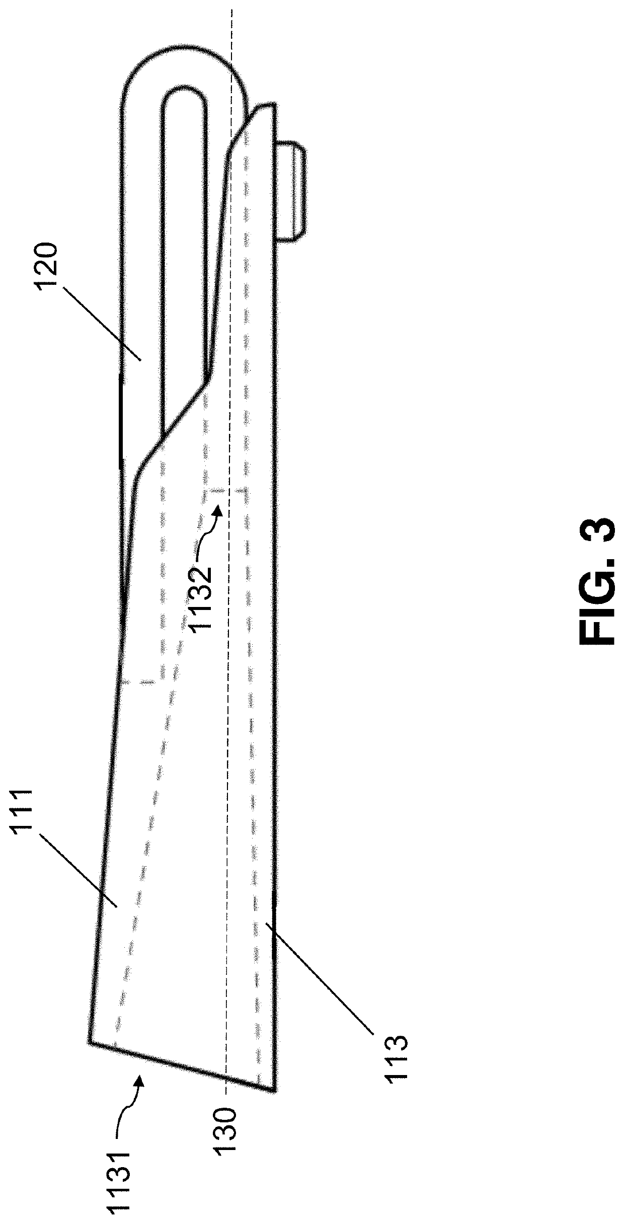
[0008]It is important to note that the light tunnel in the present invention is tapered from the front end to the rear end to enhances the effect of light concentration in the light tunnel. In other words, comparing with conventional gun sights, the size of the light tunnel can be shorted because it is tapered to enhance light concentration, and the size of the gun sight in the present invention can be further minimized without sacrificing the functionality thereof. It is also noted that the shape of the light tunnel is not limited to triangular. It can be circular or any other polygonal.

Problems solved by technology

Since any sight is mounted on top of the gun's slide, in most cases it is not perfectly aligned due to manufacturing and assembly tolerances.
Generally, the existing mechanisms are complex and expensive due to several alignment mechanical parts needed.
Also, when using the traditional “two sights” system, you need to align “two sights” which will cause more time and human error.

Method used


Image

  • Gun tunnel sight
  • Gun tunnel sight
  • Gun tunnel sight

Examples


Embodiment Construction

[0017]The detailed description set forth below is intended as a description of the presently exemplary device provided in accordance with aspects of the present invention and is not intended to represent the only forms in which the present invention may be prepared or utilized. It is to be understood, rather, that the same or equivalent functions and components may be accomplished by different embodiments that are also intended to be encompassed within the spirit and scope of the invention.

[0018]Unless defined otherwise, all technical and scientific terms used herein have the same meaning as commonly understood to one of ordinary skill in the art to which this invention belongs. Although any methods, devices and materials similar or equivalent to those described can be used in the practice or testing of the invention, the exemplary methods, devices and materials are now described.

[0019]All publications mentioned are incorporated by reference for the purpose of describing and disclos...


PUM

PropertyMeasurementUnit
concentrationaaaaaaaaaa
sizeaaaaaaaaaa
shapeaaaaaaaaaa

Abstract

In one aspect, a gun sight may include a main body and a light tube. In one embodiment, the main body may include an elongated light tunnel housing and a base, wherein the light tunnel housing is formed on top of the base, and a light tunnel is formed inside the light tunnel housing. The light tunnel has a front end and a rear end, and the light tube is disposed at the rear end. In one embodiment, the light tube can be a fluorescent optical fiber that can be used as a light source for the shooter's eye even when the environment is relatively dark. In other embodiments, the light tube can be an integration of optical fiber and tritium. The light tunnel is tapered from the front end to the rear end to enhances the effect of light concentration in the light tunnel.

Description

FIELD OF THE INVENTION[0001]The present invention relates to an aiming device used for firearms, and more particularly relates to a gun tunnel sight in which a light source creates a light spot inside a light tunnel for better aiming at the target.BACKGROUND OF THE INVENTION[0002]Firearms are conventionally aimed by using a sight installed on the firearm and pointing the sight to the target point. By “target” is meant the object or person that the shooter intends to hit, and by “target point” is meant the point of the target at which the shooter aims the projectile.[0003]Generally, the projectiles may hit any point within an area about the target point. When the sights are aligned, it defines an aim line, and when said aim line passes through the shooter's aiming eye, the axis of the firearm barrel should be substantially directed to the target point.[0004]The accuracy of guns greatly depends on the relative orientation between the aiming line of the shooter's eye and the central ax...

Claims


Application Information

Patent Timeline
Patent Type & Authority Patents(United States)
IPC IPC(8): F41G1/34F41G1/02
CPCF41G1/345F41G1/02
Inventor LEE, SHANYAO
Owner LEE SHANYAO
Why Eureka
Try Eureka