
Defect inspection device, defect inspection method, and program

a technology of defect inspection and inspection method, applied in the field of defect inspection device, defect inspection method, program, can solve the problems of difficult take time to interpret images, interfere with image interpretation, etc., to support the execution of accurate and rapid image interpretation, accurate and rapid discovery, accurate and rapid determination of defects

Active Publication Date: 2021-06-08
FUJIFILM CORP
View PDF16 Cites 0 Cited by
  • Summary
  • Abstract
  • Description
  • Claims
  • Application Information

AI Technical Summary

Benefits of technology

The present invention provides a method for quickly and accurately identifying and classifying defects in an image. The invention uses an auxiliary indication, such as image processing or a display, to clearly indicate the position and classification of a defect candidate image. The image interpreter can then efficiently interpret the image. The invention allows for precise and fast image interpretation, improving efficiency and accuracy.

Problems solved by technology

However, not all image interpreters have rich experiences and high level of knowledge, but some image interpreters may incorrectly discover a defect and discriminate a type of defect, and it may take time to interpret the image.
On the other hand, in a case where many auxiliary indications indicating defect candidate images are shown in the received light image, or in a case where the auxiliary indication is displayed to be superimposed on the defect candidate image, the displayed auxiliary indication may interfere with image interpretation and accurate and rapid image interpretation may be difficult.

Method used


Image

  • Defect inspection device, defect inspection method, and program
  • Defect inspection device, defect inspection method, and program
  • Defect inspection device, defect inspection method, and program

Examples


Embodiment Construction

[0048]Hereinafter, embodiments of a defect inspection device, a defect inspection method, and a program according to the present invention will be described with reference to the accompanying drawings.

[0049][Configuration of Defect Inspection Device]

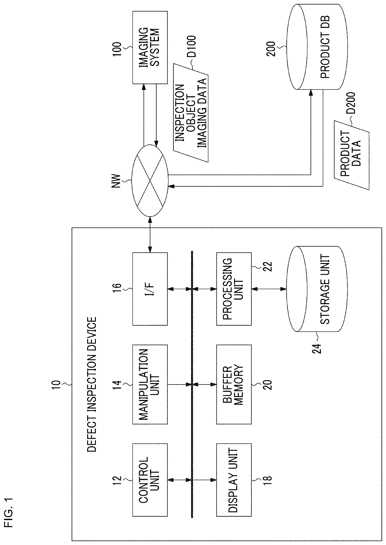
[0050]FIG. 1 is a block diagram illustrating a defect inspection device according to an embodiment of the present invention.

[0051]The defect inspection device 10 according to the embodiment is a device that detects a candidate of a defect (a defect candidate) from an image obtained by imaging an industrial product that is an inspection target (hereinafter referred to as an inspection object) and displays the defect candidate, and is a device for supporting diagnosis of the defect of the inspection object by an image interpreter. Here, the inspection object is a target of an inspection and various things are assumed. Particularly, an industrial product which is an industrial part requiring high precision design is assumed to be the inspec...


PUM

PropertyMeasurementUnit
sizeaaaaaaaaaa
sizeaaaaaaaaaa
widthaaaaaaaaaa

Abstract

An object of the present invention is to provide a defect inspection device, a defect inspection method, and a program that support an image interpreter so that image interpretation can be performed accurately and rapidly. A defect inspection device (10) includes an image acquisition unit, an image processing unit, a storage unit (24), a defect candidate classification unit that assigns a defect classification to an extracted defect candidate image on the basis of classification information stored in the storage unit (24), a display unit (18) that displays the received light image, a manipulation unit (14) that receives selection of a display or a non-display of an auxiliary indication indicating a position of the defect candidate image and the classification of the defect candidate image on the display unit (18), and outputs a command for the selected display or non-display of the auxiliary indication, and a display control unit that performs a display or a non-display of the auxiliary indication on the display unit (18) on the basis of the command output from the manipulation unit (14).

Description

CROSS-REFERENCE TO RELATED APPLICATIONS[0001]The present application is a Continuation of PCT International Application No. PCT / JP2017 / 022741 filed on Jun. 20, 2017 claiming priority under 35 U.S.C § 119(a) to Japanese Patent Application No. 2016-160770 filed on Aug. 18, 2016. Each of the above applications is hereby expressly incorporated by reference, in their entirety, into the present application.BACKGROUND OF THE INVENTION1. Field of the Invention[0002]The present invention relates to a defect inspection device, a defect inspection method, and a program, and more particularly, to a defect inspection device, a defect inspection method, and a program for supporting inspection of defects using images of industrial products that are inspection targets.2. Description of the Related Art[0003]JP2010-054365A relates to an inspection device that inspects a defect of a solar cell. JP2010-054365A discloses generating a crack identification image, a dark area identification image, and a di...

Claims


Application Information

Patent Timeline
Patent Type & Authority Patents(United States)
IPC IPC(8): G01N21/88G01N23/18G01N23/04
CPCG01N21/8851G01N21/88G01N23/04G01N23/18G01N2021/8854
Inventor KANEKO, YASUHIKO
Owner FUJIFILM CORP
Learn More