
Electrical connector of charging device

a charging device and electric connector technology, applied in the direction of securing/insulating coupling contact members, coupling device connections, fixed connections, etc., can solve the problems of increasing management difficulty in the manufacturing process, complex manufacturing process, and unstable yield of manufacturing process, so as to increase the availability of terminals

Active Publication Date: 2021-06-08
ADVANCED CONNECTEK INC
View PDF8 Cites 0 Cited by
  • Summary
  • Abstract
  • Description
  • Claims
  • Application Information

AI Technical Summary

Benefits of technology

This design simplifies the manufacturing process, reduces material waste, and enhances the applicability of semi-finished products by allowing for various specifications, while maintaining effective grounding and shielding, thus addressing the challenges of size differences and manufacturing complexities.

Problems solved by technology

Furthermore, the manufacturing process is complicated accordingly, the yield of the manufacturing process is often unstable due to the size difference, and the management difficulty to the manufacturing process is increased.

Method used


Image

  • Electrical connector of charging device
  • Electrical connector of charging device
  • Electrical connector of charging device

Examples


Embodiment Construction

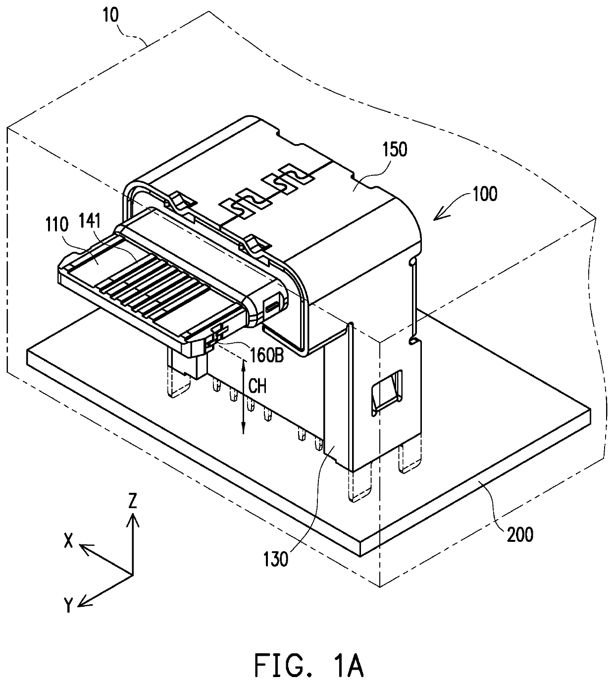
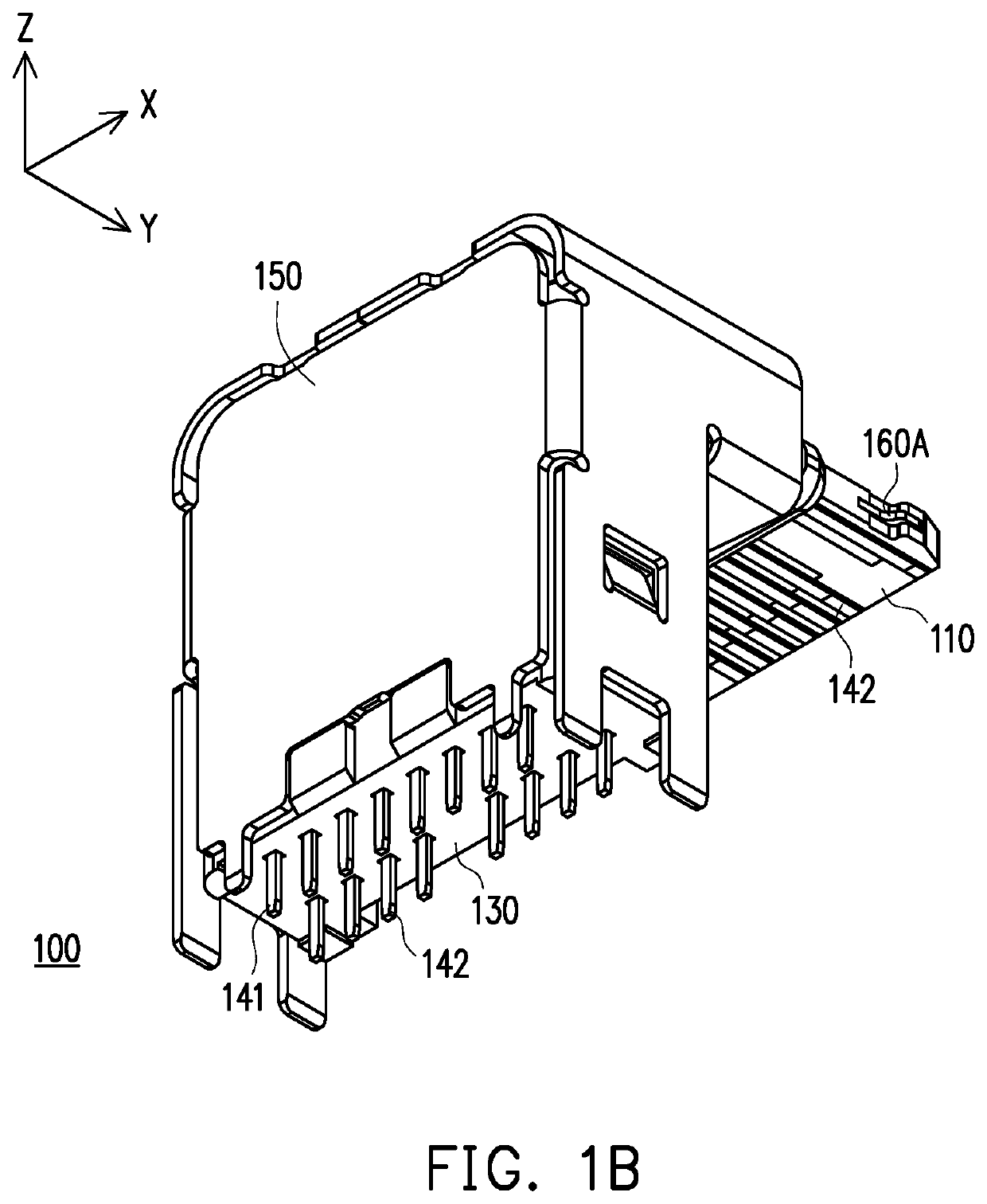
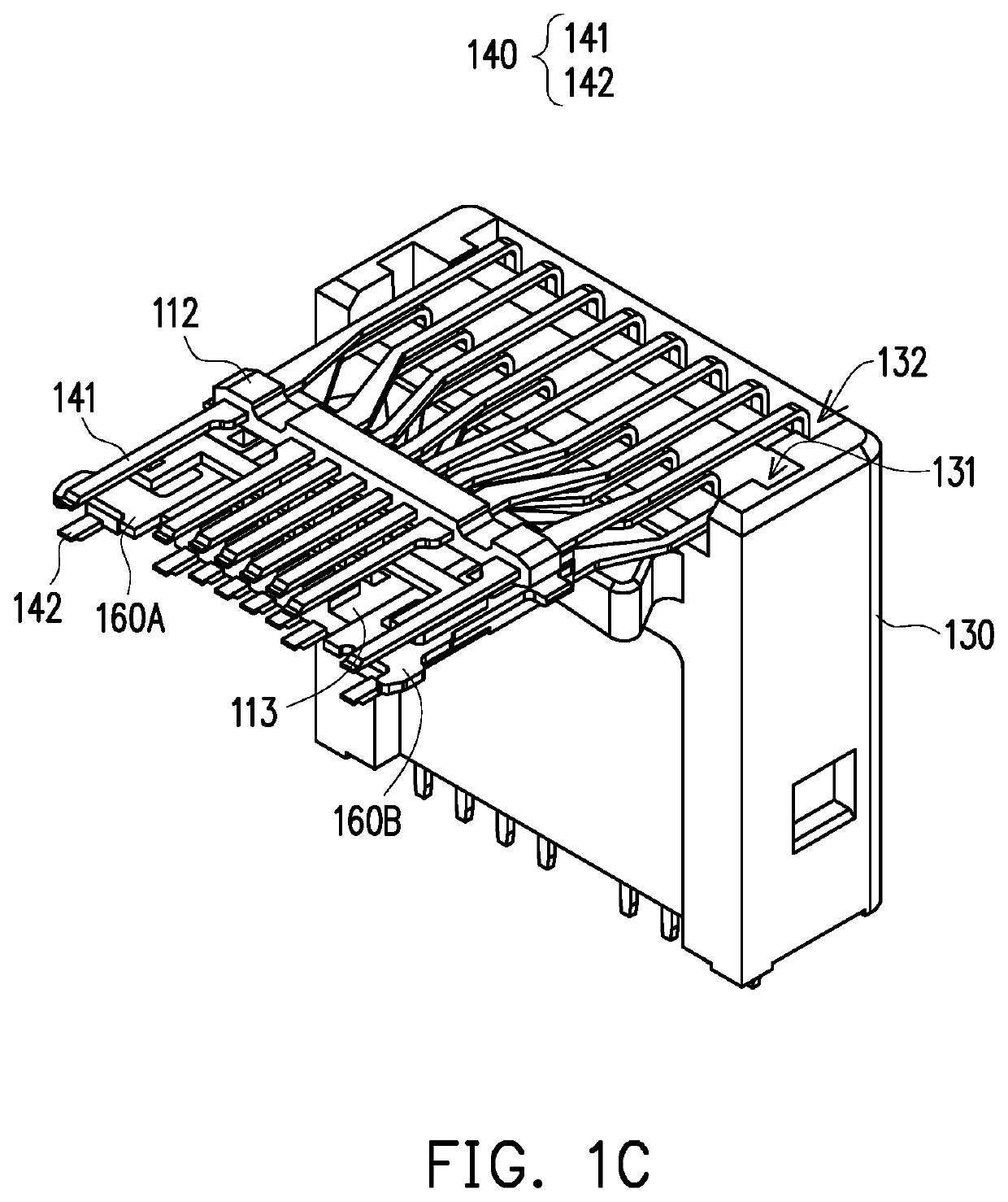
[0034]FIG. 1A is a schematic view of an electrical connector according to an embodiment of the present disclosure. FIG. 1B shows an electrical connector in FIG. 1D from another perspective. FIG. 1C is a schematic view of partial components of the electrical connector in FIG. 1A. The drawings simultaneously provide orthogonal coordinates X-Y-Z so as to facilitate the description of the related components. Referring to FIG. 1A, FIG. 1B and FIG. 1C, in the present embodiment, an electrical connector 100 is, for example, a USB Type-C connector and is disposed (soldered) on a circuit board 200 to serve as a receptacle electrical connector. Further, the electrical connector 100 of the present embodiment serves as a receptacle electrical connector of a charging device 10 to output electric power.

[0035]The electrical connector 100 includes a first insulator 110, a terminal set 140, a third insulator 130, a metallic shell 150 and two metallic plates (i.e. shielding members) 160A and 160B. Th...


PUM


Abstract

An electrical connector disposed on a circuit board is provided. The electrical connector includes a terminal set having a plurality of terminals, a first insulator, at least one second insulator, and a third insulator. Each of the terminals has a contact portion, a soldering portion connecting to the circuit board, and a bending portion connected between the contact portion and the soldering portion. The first insulator is structurally integrated with the contact portions. The second insulator is structurally integrated with the terminals and is located between the bending portions and the soldering portions. The third insulator is locked with the second insulator.

Description

CROSS-REFERENCE TO RELATED APPLICATION[0001]This application claims the priority benefit of Taiwan patent application serial no. 108206034, filed on May 15, 2019. The entirety of the above-mentioned patent application is hereby incorporated by reference herein and made a part of the specification.BACKGROUND OF THE INVENTION1. Field of the Invention[0002]The present disclosure relates to a connector, and particularly relates to an electrical connector.2. Description of Related Art[0003]An electrical connector is a common component on an electronic device and can be connected with an adapted electrical connector on another electronic device to serve as a transmission medium for signals and power between the two electronic devices. An existing electrical connector, such as a USB (Universal Serial Bus) electrical connector, is the most widely and commonly used signal transmission and charging interface at present due to a hot plug function.[0004]At present, the USB protocol additionally...

Claims


Application Information

Patent Timeline
Patent Type & Authority Patents(United States)
IPC IPC(8): H01R12/71H01R13/42H01R13/629H01R13/6594H01R12/55H01R43/02H01R12/72H01R107/00
CPCH01R12/716H01R12/55H01R12/724H01R13/42H01R13/629H01R13/6594H01R43/02H01R2107/00H01R13/405H01R13/504H01R24/60
Inventor CHIEN, MIN-LUNGHUANG, FAN-CHENGLIN, YING-TE
Owner ADVANCED CONNECTEK INC
Learn More