
Battery module for a motor vehicle

a battery module and motor vehicle technology, applied in the field of batteries, can solve the problems of reducing the usable current and the service life of the battery module, affecting the service life of the battery module, etc., and achieves the effect of increasing the resistance of the contact plate between the respective battery cells, reducing the cross-sectional area of the contact plate, and increasing the resistan

Active Publication Date: 2021-06-15
STREETSCOOTER GMBH
View PDF3 Cites 0 Cited by
  • Summary
  • Abstract
  • Description
  • Claims
  • Application Information

AI Technical Summary

Benefits of technology

The patent aims to develop a battery module for a motor vehicle that has multiple battery cells and a contact plate. The invention aims to reduce the current between battery cells in a parallel phase. The technical effect of this is to improve the overall performance and efficiency of the battery module, leading to a longer lifespan and reduced maintenance costs.

Problems solved by technology

However, the delta connection can result in currents in the longitudinal direction of the contact plate between the battery cells which are connected in parallel, which currents disadvantageously reduce the usable current and the service life of the battery module.
In addition, the currents give rise to different voltage levels at the individual battery cells of the parallel phases, as a result of which reliable operation of a vehicle which is driven by means of the battery module is not ensured and a state of health, SOH, calculation as well as calculation of the range of the electric vehicle are made difficult.

Method used


Image

  • Battery module for a motor vehicle
  • Battery module for a motor vehicle
  • Battery module for a motor vehicle

Examples


Embodiment Construction

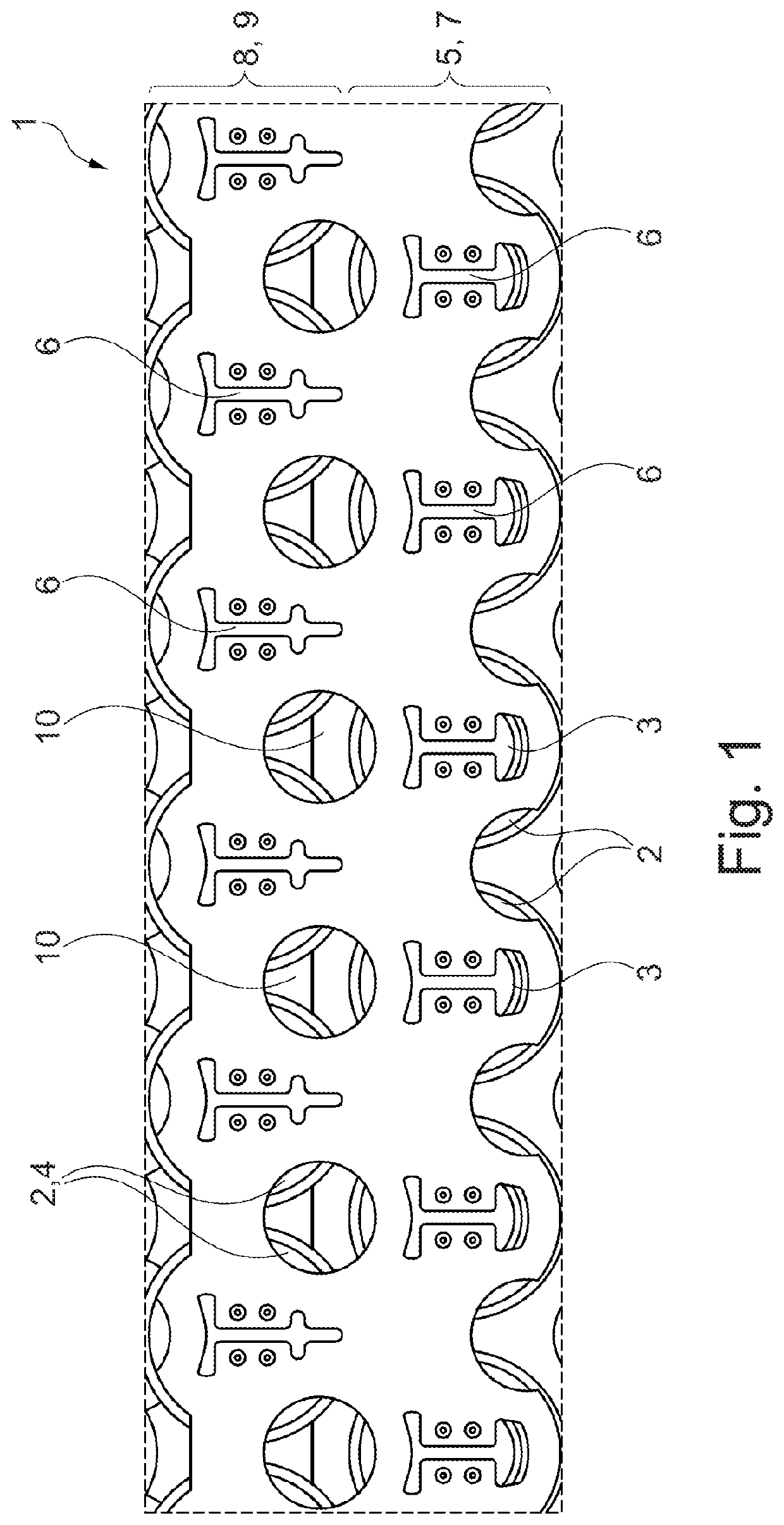
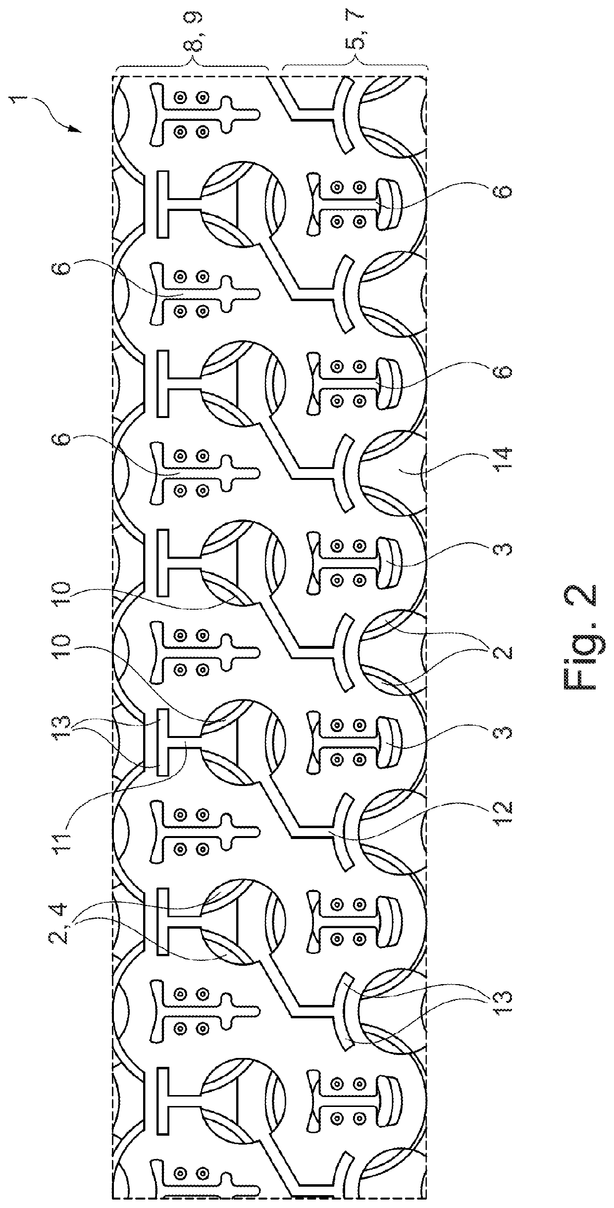
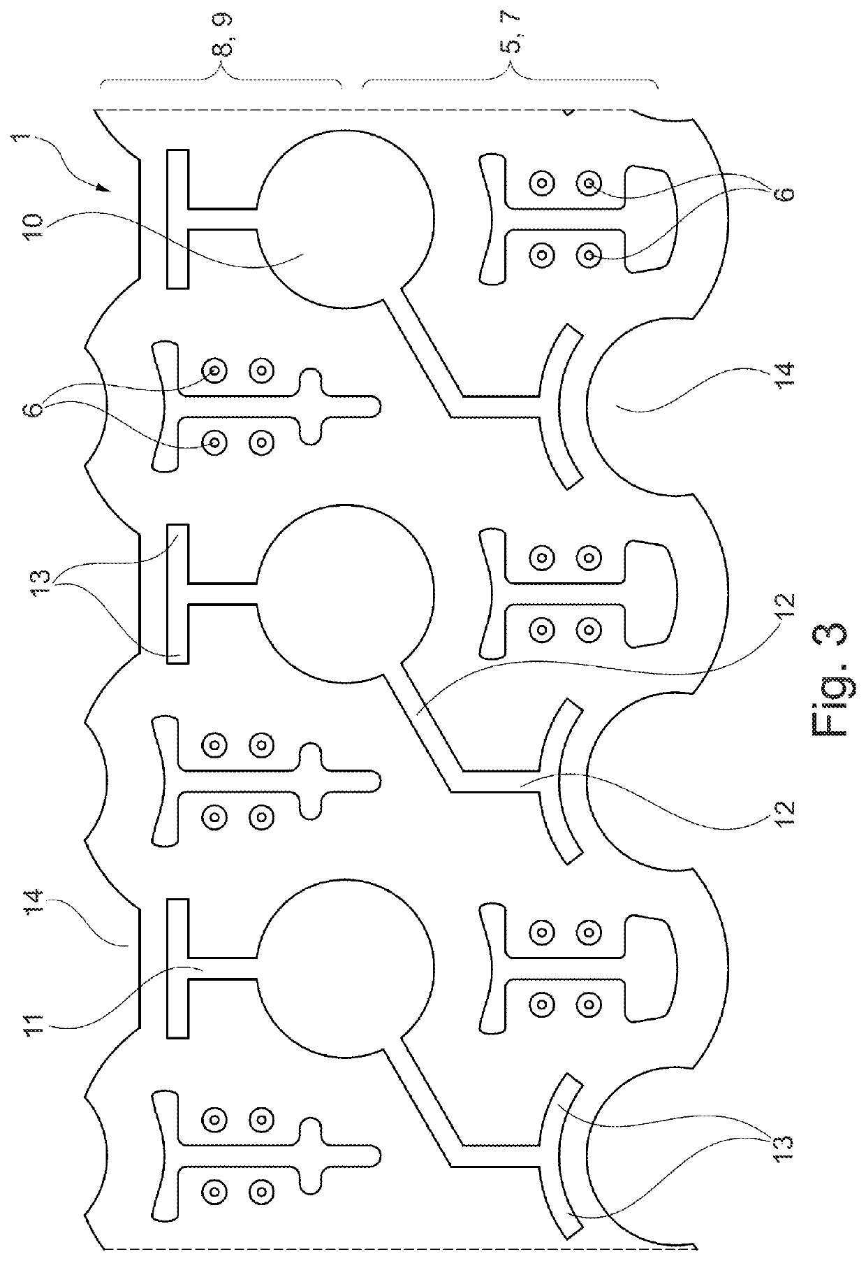
[0006]Taking this situation as a starting point, an object of the present invention is to specify a battery module for a motor vehicle having a multiplicity of battery cells and a contact plate, in which battery module currents between battery cells of a parallel phase are reduced.

[0007]The object of the invention is achieved by means of the features of the independent claims. Advantageous refinements are specified in the dependent claims.

[0008]Accordingly, the object is achieved by means of a battery module for a motor vehicle with a multiplicity of battery cells, each having a first pole and a second pole and a contact plate which extends in a transverse direction and in a longitudinal direction, wherein a first group of the battery cells are connected by their respective first pole one next to the other to a first side, extending in the longitudinal direction, of the contact plate, and a remaining second group of the battery cells are connected by their respective second pole one...


PUM

PropertyMeasurementUnit
thicknessaaaaaaaaaa
thicknessaaaaaaaaaa
thicknessaaaaaaaaaa

Abstract

The subject matter of the invention is a battery module for a motor vehicle having a multiplicity of battery cells, each having a first pole and a second pole and a contact plate which extends in a transverse direction and in a longitudinal direction, wherein a first group of the battery cells are connected via their respective first pole, one after the other to a first side, extending in the longitudinal direction, of the contact plate, and a remaining second group of the battery cells are connected by their respective second pole, one after the other to a second side, extending in the longitudinal direction, of the contact plate, with the result that, by means of the contact plate the first group of the battery cells are connected via the first poles, and the second group of the battery cells are connected via the second poles, in parallel, and the first group of the battery cells and the second group of the battery cells are connected in series, and between adjacent first poles on the first side and / or between adjacent second poles on the second side, at least one cutout, extending in the transverse direction, is provided in the contact plate, with a length such that the ratio of the resistance of the contact plate in the extent in the longitudinal direction with respect to the resistance of the contact plate in the extent in the transverse direction is ≥2.

Description

CROSS-REFERENCE TO RELATED APPLICATIONS[0001]This application claims the benefit of German Patent Application No. 10 2018 107 091.8 filed Mar. 26, 2018, which is hereby incorporated by reference.TECHNICAL FIELD[0002]The invention relates to a battery module having a multiplicity of battery cells, each having a first pole and a second pole and a contact plate which extends in a transverse direction and in a longitudinal direction. In addition, the invention relates to a method for reducing currents in the longitudinal direction of a contact plate, extending in a transverse direction and in the longitudinal direction, of a battery module for a motor vehicle, with which battery module a multiplicity of battery cells, each having a first pole and a second pole, can be connected.BACKGROUND OF THE INVENTION[0003]According to the latest estimates, it is expected that in Germany alone there will be a million electric vehicles by 2020, wherein the majority of purely electrically driven vehic...

Claims


Application Information

Patent Timeline
Patent Type & Authority Patents(United States)
IPC IPC(8): H01M2/20H01M2/10H01M2/34H01M50/502H01M50/20H01M50/572H01M50/528H01M50/213H01M50/503H01M50/509
CPCH01M50/502H01M50/20H01M50/572H01M2220/20Y02E60/10H01M50/528H01M50/503H01M50/509H01M50/213
Inventor HARTMANN, STEPHANARMBRUSTER, NILSMOULIAÀ, ALEJANDRO LORCA
Owner STREETSCOOTER GMBH
Learn More