
LED AC driving circuit capable of adjusting operating voltage

a driving circuit and operating voltage technology, applied in the direction of electric variable regulation, process and machine control, instruments, etc., can solve the problems of voltage-controlled transistors b>22/b> encountering the problem of overheating, and conventional ac led driving circuits are unsuitable for particular applications with high operating voltages

Inactive Publication Date: 2014-09-30
LUXUL TECH
View PDF3 Cites 0 Cited by
  • Summary
  • Abstract
  • Description
  • Claims
  • Application Information

AI Technical Summary

Benefits of technology

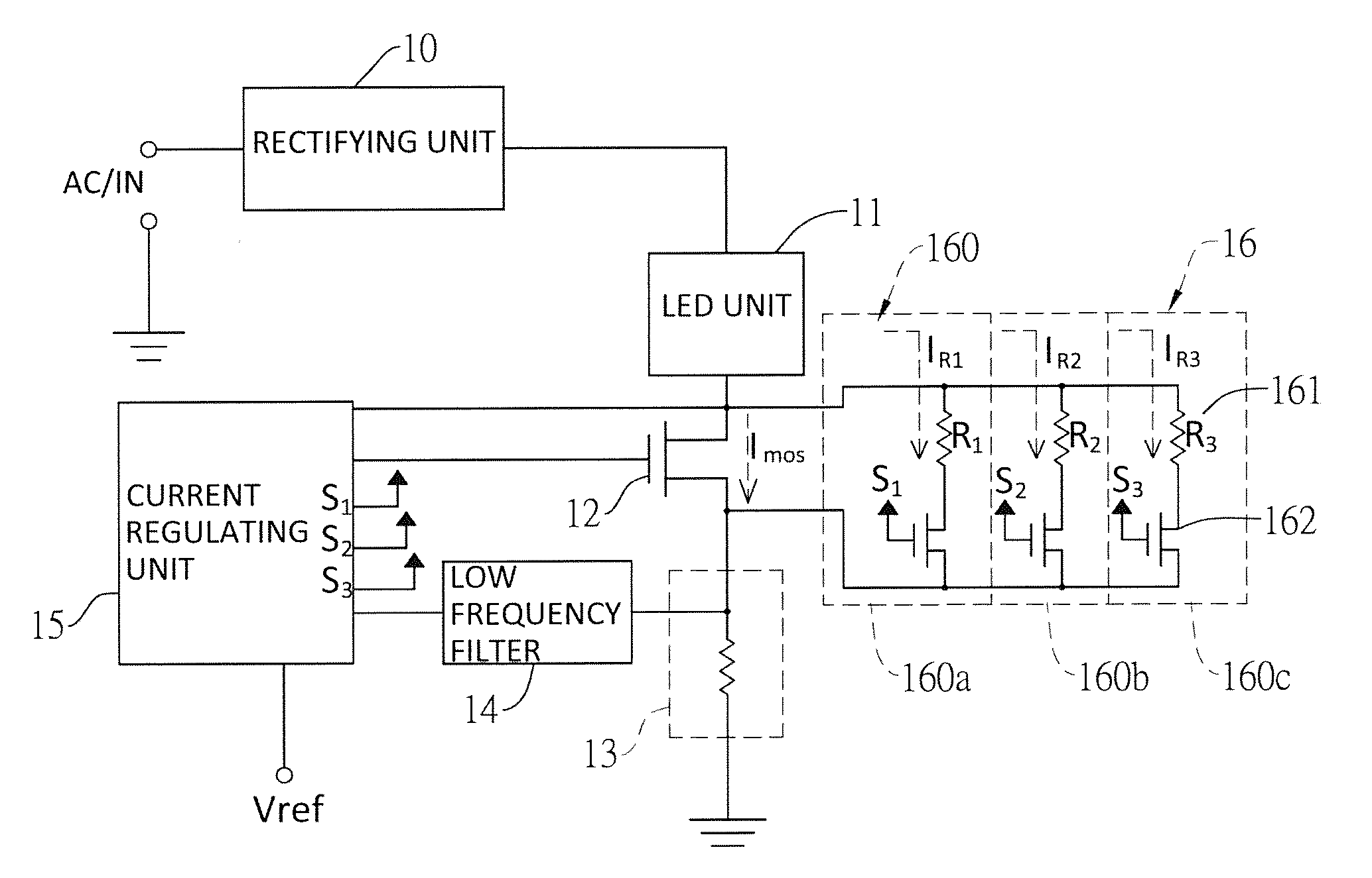
[0024]wherein the current regulating unit compares the voltage from the low frequency filter with the reference voltage to produce a control signal applied to the control terminal of the voltage-controlled transistor for stabilizing the loop current, and detects operating power of the voltage-controlled transistor for controlling the resistance adjusting unit to change the resistance across the voltage-controlled transistor.
[0025]With the foregoing circuit configuration, the current regulating unit will continuously detect the operating power of the voltage-controlled transistors and adjust the resistance of the resistance adjusting unit based on the detected result. In one aspect, the current through the voltage-controlled transistor will be increased when the operating power is zero. In another aspect, the current through the voltage-controlled transistor will be decreased when the operating power is larger than the maximum rated power. By properly adjusting the resistance, the operating power can be maintained between zero and the maximum rated power.

Problems solved by technology

Limited by the one-way driving characteristic of the LED, the LED lights cannot be connected to AC sockets directly.
However, the voltage-controlled transistor 22 may encounter the problem of over-heating because it is connected in the power loop and sustains a large power.
Therefore, it seems that the conventional AC LED driving circuit is unsuitable for particular applications with high operating voltages.

Method used


Image

  • LED AC driving circuit capable of adjusting operating voltage
  • LED AC driving circuit capable of adjusting operating voltage
  • LED AC driving circuit capable of adjusting operating voltage

Examples


first embodiment

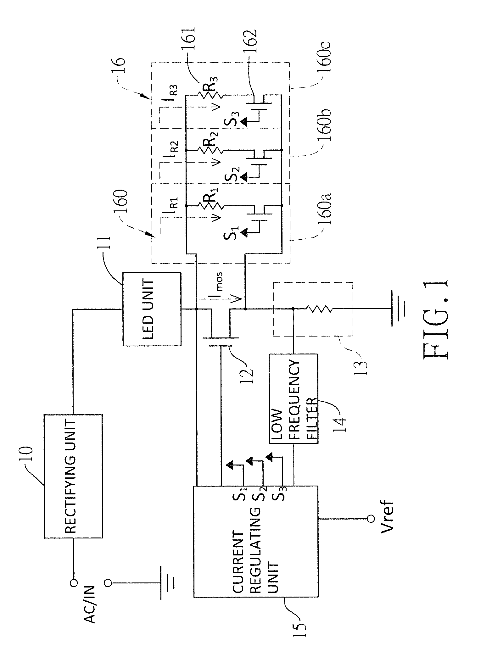
[0054]With reference to the first embodiment as shown in FIG. 1, the resistance adjusting unit 16 comprises a first, a second, and a third current-shunting unit 160a-160c connected in parallel. The resistances values R1-R3 of the three shunt resistors 161 are respectively 150, 180 and 220 ohms. Each shunt resistor 161 connects its first end to the respective control transistor 162, and its second end to the drain of the voltage-controlled transistor 12. The sources of all the control transistors 162 and the voltage-controlled transistor 12 are connected together.

[0055]In the first embodiment, the detecting terminal of the current regulating unit 15 is connected to the node between the LED unit 11 and the voltage-controlled transistor 12. The current regulating unit 15 calculates the operating power of the voltage-controlled transistor 12 by referring to the operating voltage of the voltage-controlled transistor 12 currently detected at the detecting terminal, and also referring to t...

second embodiment

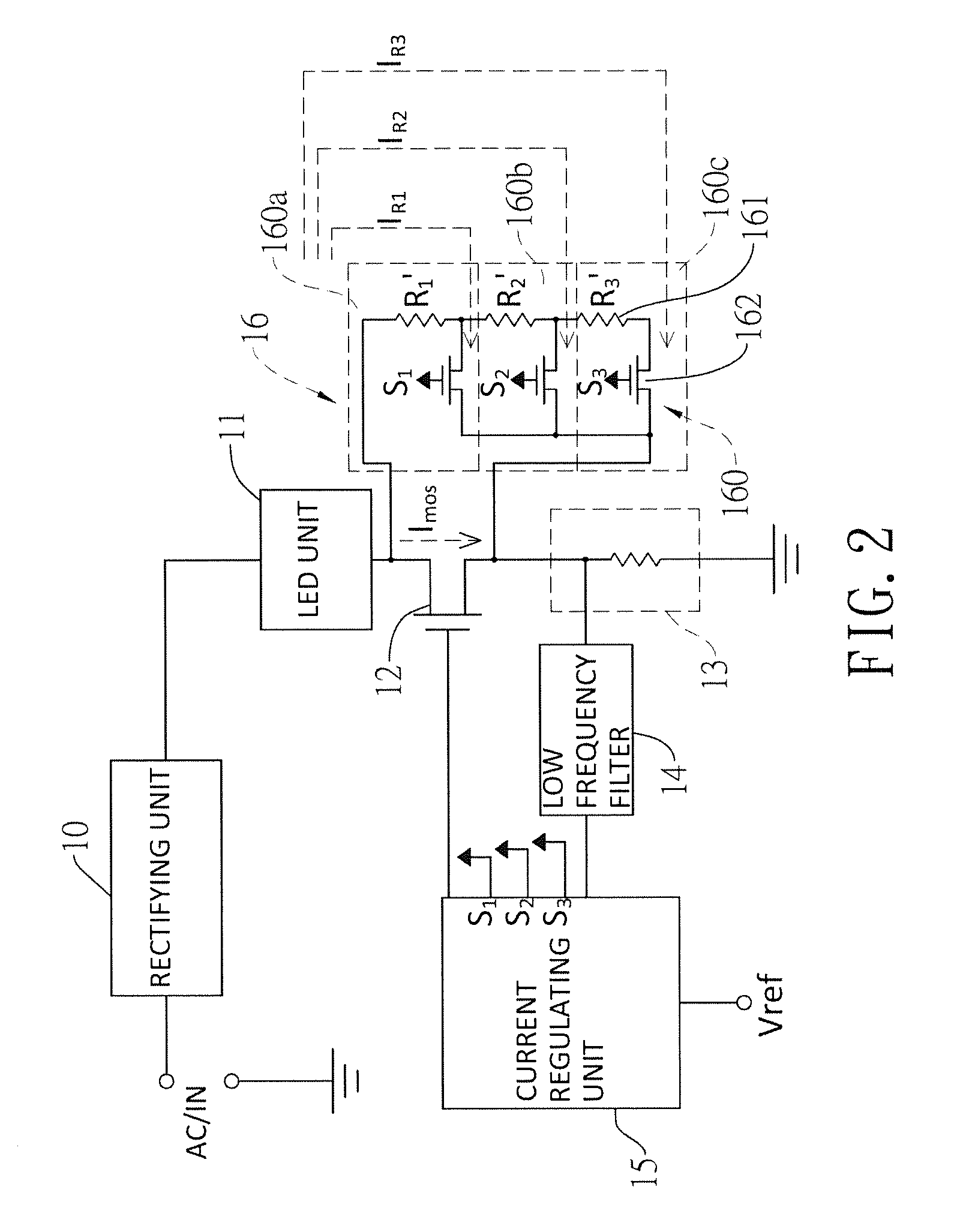
[0058]With reference to the second embodiment as shown in FIG. 2, the three shunt resistors 161 are connected in series. The first shunt resistor is connected between both the drains of the voltage-controlled transistor 12 and the control transistor 162 of the first current-shunting unit 160a. The second shunt resistor is connected between both the drains of the two control transistors 162 of the first and second current-shunting units 160a, 160b. The third shunt resistor is connected between both the drains of the two control transistors 162 of the second and third current-shunting units 160b, 160c.

[0059]All the sources of the control transistors 162 are connected to the source of the voltage-controlled transistor 12. The resistance values R1-R3 of the three shunt resistors 161 are respectively 150, 30 and 40 ohms.

[0060]In the second embodiment, the input terminal of the current regulating unit 15 also acts as the detecting terminal thereof. When the operating voltage of the volta...

third embodiment

[0066]With reference to the third embodiment as shown in FIG. 3, a power detecting resistor 17 is added between the LED unit 11 and the current detecting unit 13. The current regulating unit 15 further has a second detecting terminal and a third detecting terminal. The second detecting terminal is connected to a node between the voltage-controlled transistor 12 and the power detecting resistor 17. The third detecting terminal is connected to another node between the LED unit 11 and the voltage-controlled transistor 12.

[0067]The second input terminal and the third input terminal are connected to the voltage-controlled transistor 12 in parallel to detect the operating voltage of the voltage-controlled transistor 12. Because the power detecting resistor 17 is connected in series to the voltage-controlled transistor 12, the current going through the voltage-controlled transistor 12 is detectable at the detecting terminal. The current-regulating unit 15 can calculate the operating power ...


PUM


Abstract

An LED AC driving circuit capable of adjusting operating voltage has a rectifying unit, an LED unit, a voltage-controlled transistor, a current detecting unit and a current regulating unit to form a power loop. Further, a resistance adjusting unit is connected to the voltage-controlled transistor in parallel. The current regulating unit detects the operating power of the voltage-controlled transistor. When the detected operating power is zero, the resistance of the resistance adjusting unit is increased for increasing the current flowing through the voltage-controlled transistor. When the detected operating power becomes larger than a maximum rated power, the resistance of the resistance adjusting unit is decreased to reduce the current. Thus, the operating power is maintained between zero and the maximum rated power.

Description

CROSS-REFERENCE TO RELATED APPLICATIONS[0001]This application claims the benefit of Taiwan patent application No. 101102573, filed on Jan. 20, 2012, and Taiwan patent application No. 101103735, filed on Feb. 6, 2012, the disclosures of which are incorporated herein in their entirety by references.BACKGROUND OF THE INVENTION[0002]1. Field of the Invention[0003]The present invention relates to an LED AC driving circuit, particularly an LED AC driving circuit capable of adjusting an operating voltage.[0004]2. Description of the Prior Art[0005]LED lights as the popular and common lighting devices have the advantages of high illumination efficiency and low power consumption in comparison to the incandescent light. Limited by the one-way driving characteristic of the LED, the LED lights cannot be connected to AC sockets directly. One of the conventional LED AC driving circuits as shown in FIG. 9 is proposed to overcome the limitation.[0006]The LED AC driving circuit comprises a rectifying...

Claims


Application Information

Patent Timeline
Patent Type & Authority Patents(United States)
IPC IPC(8): H05B37/02H05B44/00
CPCH05B37/02H05B33/0812Y02B20/345H05B45/395Y02B20/30
Inventor PAN, CHENG-HUNG
Owner LUXUL TECH
Learn More