
DC motor having enhanced startability

a dc motor and startability technology, applied in the direction of engine starters, electric generator control, machines/engines, etc., can solve the problems of increasing the number of component ports and production costs of dc motors, and achieve the effects of reducing the effect of voltage commutation, ensuring the stability of engagement, and enhancing the effect of commutation improvemen

Inactive Publication Date: 2011-08-02
DENSO CORP
View PDF21 Cites 0 Cited by
  • Summary
  • Abstract
  • Description
  • Claims
  • Application Information

AI Technical Summary

Benefits of technology

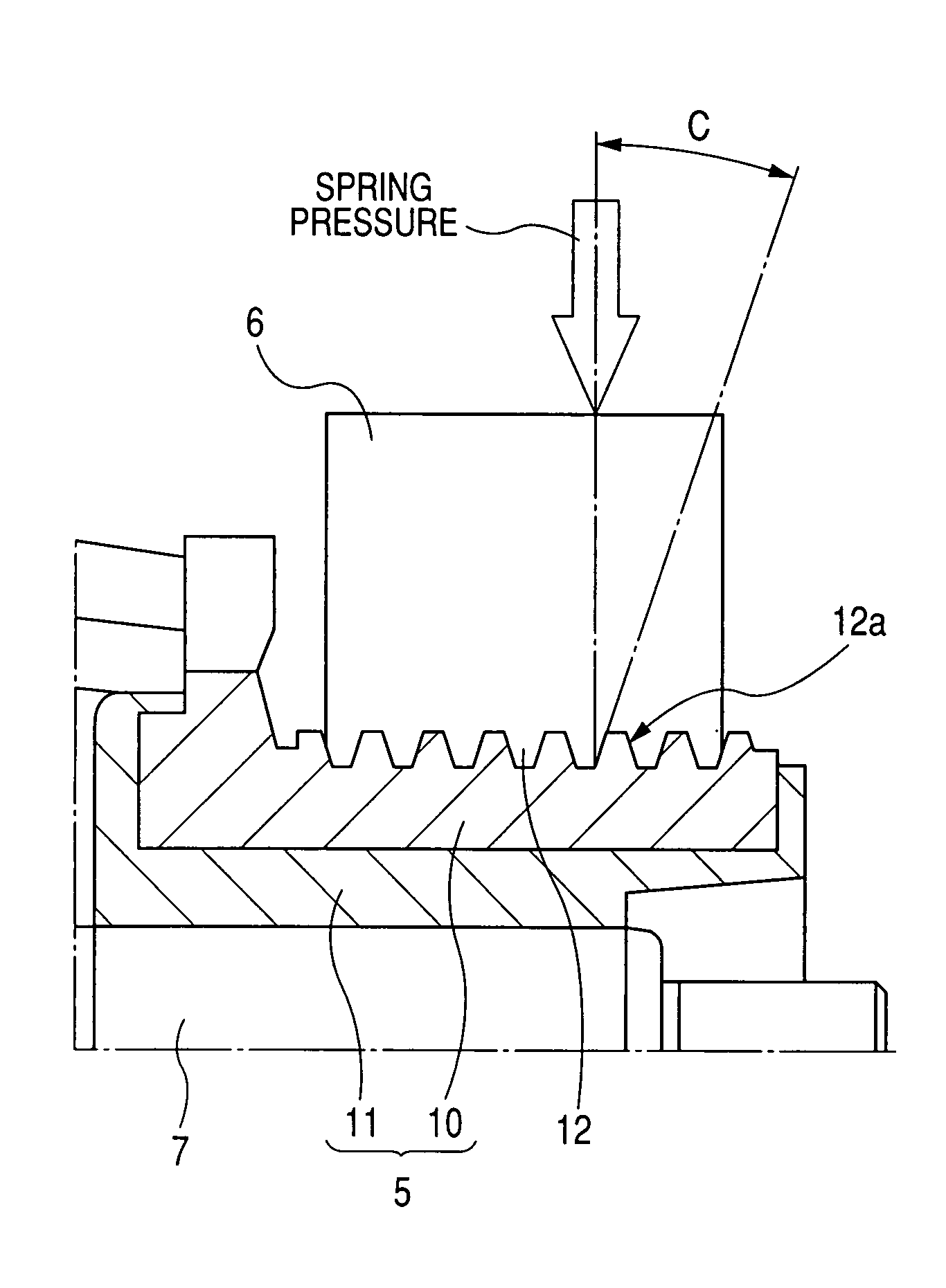
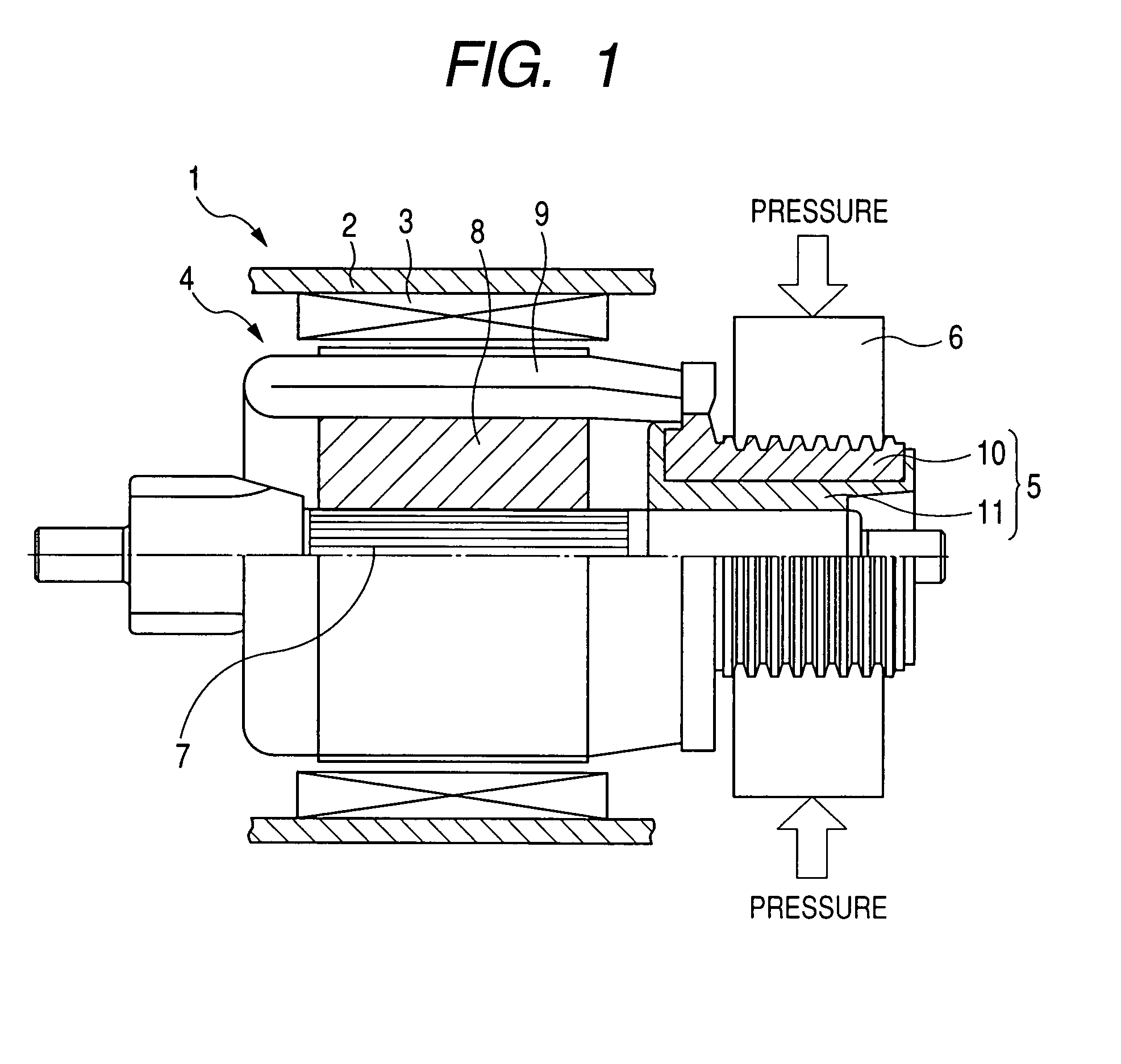
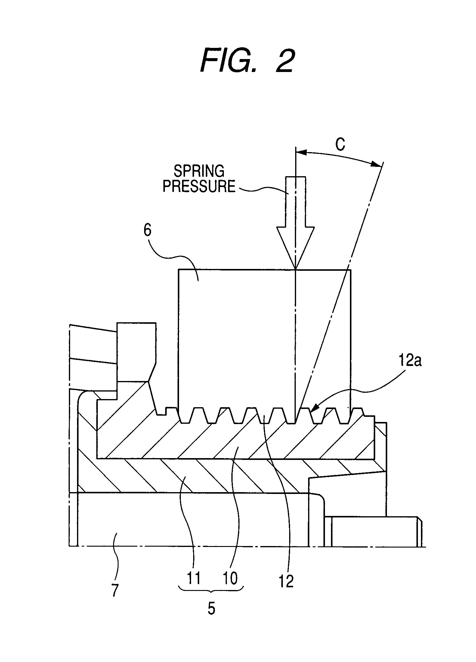
[0011]The protrusions on the commutator surface serve to ensure the stability of engagement of the brush 6 with the commutator surface, thereby enhancing the effects of improvement on the commutation (will also be referred to as voltage commutation below) which cancel the reactance voltage, as produced during the commutation, by the electromotive force, as produced by the coils 9 immediately before the commutation. This causes the distribution of current flowing between the brush and the commutator surface in a low-current range to be biased toward an upstream portion (i.e., a leading portion) of the brush in a direction of rotation of the armature, thereby producing substantially the same effects as those in the case where the angle of brush shift is changed in a conventional structure.
[0012]In a high-current range, the current density in the brush increases, thereby reducing the effects of the voltage commutation so that the output performance of the dc motor will be identical with those in typical dc motors. Specifically, the structure of the dc motor of the invention serves to improve the speed of rotation thereof without use of the auxiliary poles in the conventional structure, as discussed in the introductory part of this application, thus enhancing the startability of the dc motor at room temperatures at decreased costs.
[0013]The inclination of the side walls of the protrusions to the direction in which the brush is urged elastically enhances the efficiency in exerting the elastic pressure on the side walls, thus resulting in the stability of sliding motion of the brush in contact with the commutator surface to enhance the improvement of the speed of rotation of the armature in the low-current range.
[0017]The brush has a sliding surface placed in sidable contact with the commutator surface. The sliding surface has a width B extending in the first direction. Each of the protrusions has a top surface defined between the side walls. A total width L that is the sum of widths of the top surfaces of the protrusions lying within the width B is selected to meet a relation of L / B≦1 / 2. When the brush is initially placed in the constant engagement with the commutator surface, the sliding surface of the brush is substantially shaped to conform to a contour of the commutator surface in a circumferential direction thereof. Specifically, the width B of the brush and the total width L of the top surfaces meeting the relation of L / B≦1 / 2 result in initial exertion of the elastic pressure on the sliding surface the brush which is two or more times greater than that when the sliding surface of the brush is worn, so that it conforms to the protrusion, thus ensuring the stability of engagement of the brush with the commutator surface.

Problems solved by technology

The above structure, however, has the drawback in that the auxiliary poles are magnetized during energization of the armature coils to produce magnetic attraction between the auxiliary poles and an armature, thus requiring the need for securing the auxiliary poles to a yoke against the magnetic attraction.
Additionally, as compared with motors equipped with the auxiliary poles, the above dc motor also has the problems of increases in number of component ports and production cost thereof.

Method used


Image

  • DC motor having enhanced startability
  • DC motor having enhanced startability
  • DC motor having enhanced startability

Examples


second embodiment

[0047]FIG. 4 illustrates the brushes 6 and the commutator 5 installed in the starter motor 1 according to the invention.

[0048]The width B of each of the brushes 6, that is, the distance between opposed sides of the bottom surface (will also be referred to as a sliding surface below) of the brush 6 placed in slidable contact with the surface of the commutator 5, as defined in the axial direction of the commutator 5 (i.e., the lateral direction in the drawing) and a total width L that is the sum of widths A of the top surfaces 12b of the ridges, as defined by the grooves 12 of the commutator 5, within the width B are selected to meet a relation of L / B≦=1 / 2. In the illustrated case, since six of the top surfaces 12b of the ridges lie within the width B, the total width L will be 6×A.

[0049]The sliding surface of each of the brushes 6 is machined to have an even surface curved in concave form in the direction of rotation of the commutator 5, as illustrated in FIG. 5, before installed in ...

first embodiment

[0054]Other arrangements are identical with those in the first embodiment, and explanation thereof in detail will be omitted here.

third embodiment

[0055]FIG. 7 is a partially sectional view which shows the brushes 6 and the armature 4 according to the invention which may be installed in the starter 1, as illustrated in FIG. 1.

[0056]The armature 4 has the commutator 5 extending perpendicular to the axis of the armature shaft 7. Specifically, a portion of each of the armature coils 9 extending outside one of slots 20 of the armature core 8 is disposed in parallel to an end surface of the armature core 8 to form one of the commutator segments 10.

[0057]The armature coils 9 is made up of as many combinations of lower coil layers 90 and upper coil layers 91 as the slots 20 formed in the armature core 8. Each of the lower coil layers 90 has a straight section. Similarly, each of the upper coil layers 91 has a straight section. Each of the straight sections is laid to overlap with one of the straight sections within one of the slots 20. An end of each of the lower coil layers 90 extending outside one of the slots 20 is joined to an en...


PUM


Abstract

A dc motor is provided which is equipped with brushes each of which is urged by a spring pressure into constant abutment with a commutator surface. A plurality of protrusions are arrayed on the commutator surface in a direction perpendicular to a direction in which a commutator is to be rotated and extend over a whole of a circumference of the commutator surface. Each of the protrusions is defined by two side walls arrayed adjacent each other. At least one of the two side walls of each of the protrusions is oriented to be inclined at a preselected angle to the orientation of the spring pressure. The preselected angle lies within a range of 20° to 70°. This ensures the stability of the abutment of the brush with the commutator surface, thus enhancing the startability of the dc motor.

Description

CROSS REFERENCE TO RELATED DOCUMENT[0001]The present application claims the benefits of Japanese Patent Application No. 2006-317095 filed on Nov. 24, 2006, the disclosure of which is incorporated herein by reference.BACKGROUND OF THE INVENTION[0002]1. Technical Field of the Invention[0003]The present invention relates generally to a dc motor equipped with permanent magnets used as field magnets, and more particularly to an improved structure of such a motor designed to have enhanced startability thereof.[0004]2. Background Art[0005]Japanese Patent Second Publication No. 5-10903 teaches techniques for improving the speed of a dc motor equipped with permanent magnets in a low-current range without sacrificing the torque output in a high-current range in order to enhance the startability thereof at room temperature. Specifically, the structure, as taught in such a publication, has magnetic material-made auxiliary poles each of which is disposed on a magnetizing side of one of permanent...

Claims


Application Information

Patent Timeline
Patent Type & Authority Patents(United States)
IPC IPC(8): H02K13/10
CPCH01R39/381
Inventor HIRABAYASHI, TAKASHI
Owner DENSO CORP
Learn More