Anti-rapid drop bicycle rack and its anti-rapid drop joint

a bicycle rack and anti-rapid technology, applied in the field of bicycle rack technology, can solve the problems of large weight of the second coupling, very high risk of the whole bicycle rack falling off when it is swung down, and large weight of the entire bicycle rack, so as to effectively protect the bicycle rack itself from damage, avoid injury to personnel, and more secure and durable

Active Publication Date: 2021-06-29
JYIN SHENG CO LTD HUATAN TOWNSHIP
View PDF17 Cites 2 Cited by
  • Summary
  • Abstract
  • Description
  • Claims
  • Application Information

AI Technical Summary

Benefits of technology

[0005]The present invention has been accomplished under the circumstances in view. It is the main object of the present invention to provide an anti-rapid drop bicycle rack and its anti-rapid drop joint, which can add a mechanism that can be stopped during the swinging of the bicycle rack from the standing position to the most inclined position, so that the bicycle rack will not fall from the standing state to the most inclined state at one time, but will stop in the middle stroke to avoid injury to the personnel and to effectively protect the bicycle rack itself against damage, making the bicycle rack more secure and durable.
[0008]In actual use of an anti-rapid drop joint for bicycle rack provided by the present invention and an anti-rapid drop bicycle rack using the anti-rapid drop join, the arrangement of the intermediate positioning groove allows the hollow body to be swung from a standing state to an inclined state, and the hollow body will be stopped halfway if the handle is not operated by a person during the swinging movement of the hollow body from the standing state to the inclined state. Thereby, the main body of the bicycle rack will not be directly dropped from the standing state to the most inclined state at one time, and will stop in the middle stroke, avoiding injury to the person, and can effectively protect the bicycle rack itself, making the bicycle rack safer and more durable.

Problems solved by technology

However, since the aforementioned second coupling connects the main body of the entire bicycle rack, the entire bicycle rack has a considerable weight.
When a bicycle is disposed on the entire bicycle rack, the weight carried on the second coupling is very large.
In this way, when the second coupling is to be changed from the vertical position to the horizontal position, if the operator does not hold the upright stanchion (referenced by 121) or the structure connected thereto to move it down slowly, the whole bicycle rack is very likely to fall sharply when it is swung down, because of its large body weight.
This is very likely to injure the operator or cause the second slip seat (22) to be damaged by a powerful impact.

Method used


Image

  • Anti-rapid drop bicycle rack and its anti-rapid drop joint
  • Anti-rapid drop bicycle rack and its anti-rapid drop joint
  • Anti-rapid drop bicycle rack and its anti-rapid drop joint

Examples


Embodiment Construction

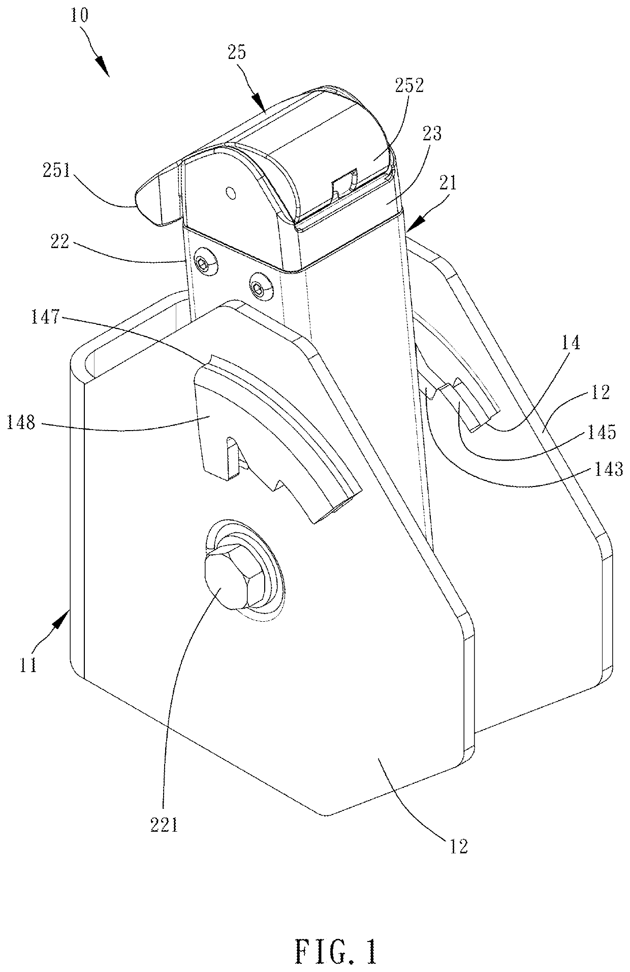
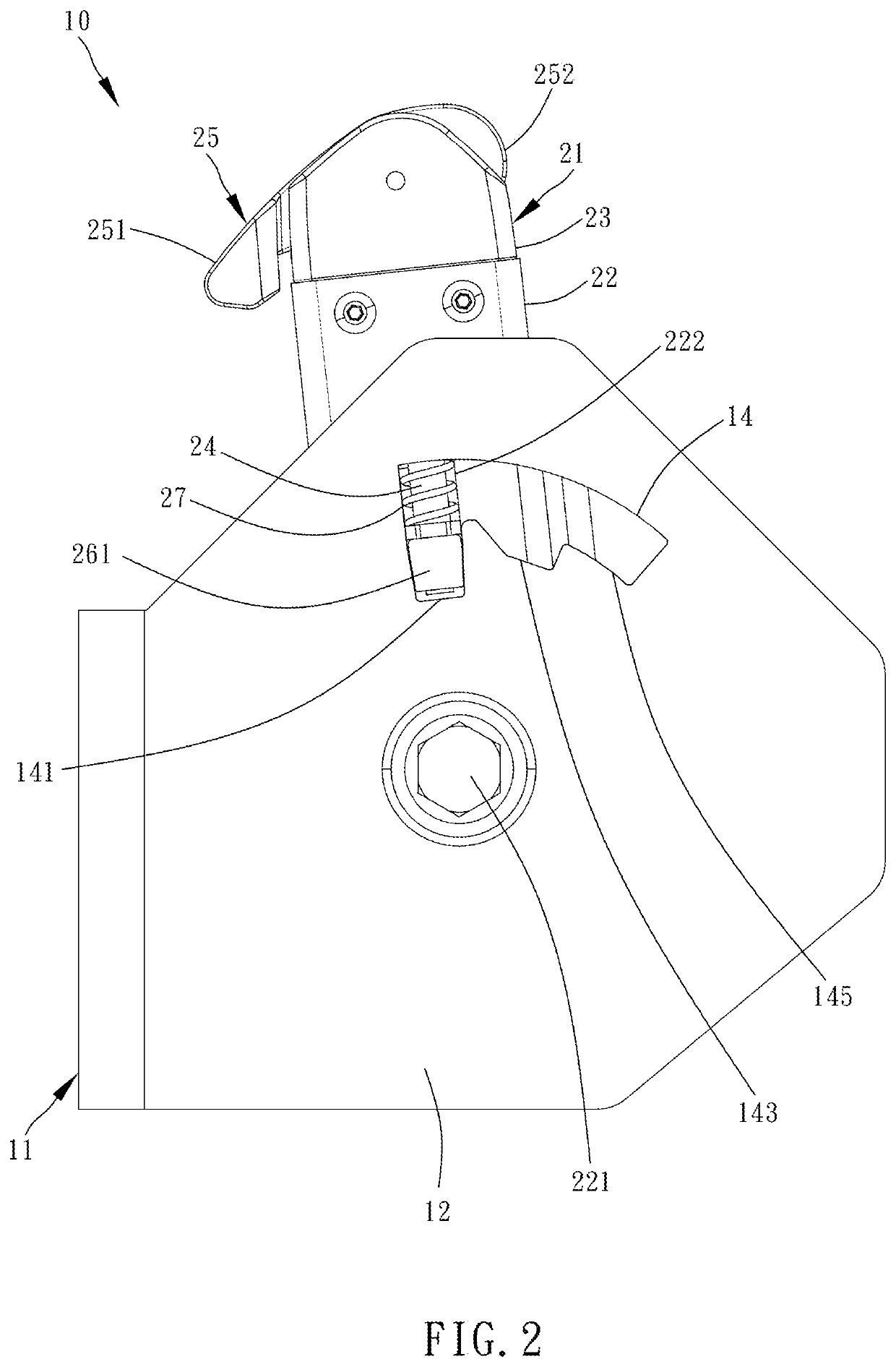
[0022]Referring to FIGS. 1-5, an anti-rapid drop 10 for bicycle rack in accordance with the present invention is shown. The anti-rapid drop joint 10 mainly consists of a holder block 11 and a swing assembly 21.

[0023]The holder block 11 mainly comprises two upright plates 12, and the two upright plates 12 are parallel to each other and separated by a predetermined distance. The two upright plates 12 of the holder block 11 respectively have a guiding hole 14, the guiding holes 14 of the two upright plates 12 are opposite to each other.

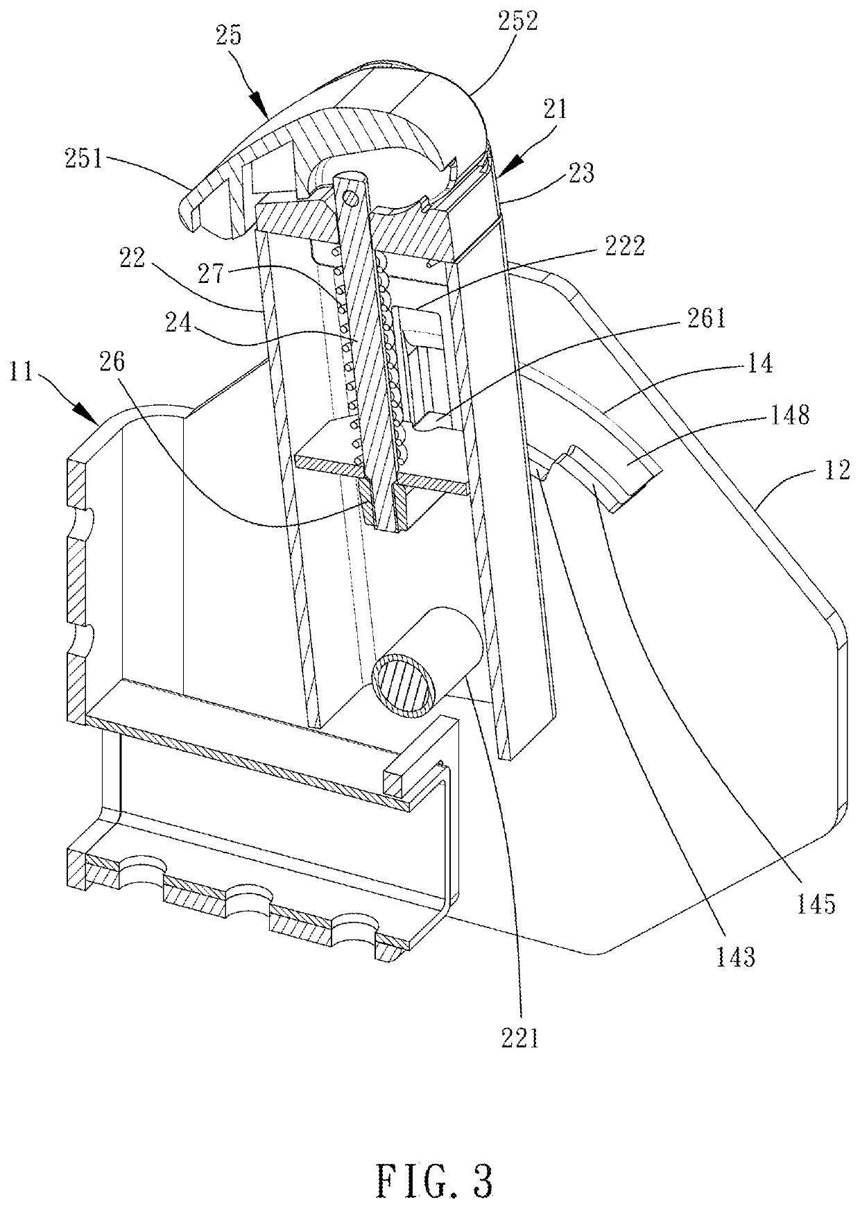
[0024]The swing assembly 21 is pivoted to the two upright plates 12 and located between the two upright plates 12. The swing assembly 21 comprises a hollow body 22, a mount 23, an actuating rod 24, a handle 25, an interference member 26 and a spring 27.

[0025]The hollow body 22 is a tubular member pivoted to the two upright plates 12 by a pivot 221, and the hollow body 22 has a through hole 222 on each of two opposite sides thereof. The mount 23 is locate...


PUM


Abstract

An anti-rapid drop bicycle rack and its joint in which the joint provides an anti-rapid drop function. The joint includes a holder block having two upright plates and a guiding hole on each upright plate, and a swing assembly including a hollow body, a mount, an actuating rod, a handle, an interference member and a spring. The bottom edge of each guiding hole defines a standing positioning groove at the front side, an inclined positioning groove at the rear side, and an intermediate positioning groove between the standing positioning groove and the inclined positioning groove. The interference member is elastically abutted against the groove bottom of one of the standing positioning groove, the inclined positioning groove and the intermediate positioning groove of each of the two guiding holes.

Description

BACKGROUND OF THE INVENTION1. Field of the Invention[0001]The present invention relates to bicycle rack technology and more particularly, to an anti-rapid drop bicycle rack and its anti-rapid drop joint.2. Description of the Related Art[0002]Taiwan Patent No. I642573 discloses a bicycle rack, in which the second sliding block (referenced by 45) is elastically inserted into one positioning groove (referenced by 223, 224) in a second sliding arch slot (referenced by 222) between the second coupling (referenced by 41) and the second slip seat (referenced by 22). When the second sliding block is inserted in the positioning groove (223), the second coupling is held in vertical. When the second sliding block is inserted in the positioning groove (224), the second coupling is turned down to a horizontal state. By means of mounting the second sliding block in one of the two positioning grooves, the second coupling is set in vertical or horizontal. When the second coupling is to be changed f...

Claims


Application Information

Patent Timeline
Patent Type & Authority Patents(United States)
IPC IPC(8): B62H3/00B60R9/10
CPCB62H3/00B60R9/10
Inventor TSAI, YU-LUNG
Owner JYIN SHENG CO LTD HUATAN TOWNSHIP
Why Eureka
Try Eureka