
Screw press

a screw press and screw technology, applied in the field of screw presses, can solve the problems of affecting the performance of the screw press, the abrasion of the screw shaft, and the disadvantages of certain conveying materials, chemical pulp fibers or fiber stock suspensions, etc., and achieves the effects of low weight, high flexibility of composite materials, and special fast and easy application of surface sections

Active Publication Date: 2021-07-06
ANDRITZ AG
View PDF11 Cites 1 Cited by
  • Summary
  • Abstract
  • Description
  • Claims
  • Application Information

AI Technical Summary

Benefits of technology

The invention is a screw press that solves the problems of existing designs by making it easy and inexpensive to change the materials used on the rough surface of the screw shaft.

Problems solved by technology

The problematical aspect of generic screw presses is that the screw shaft is exposed to severe abrasion from the conveying material transported in the transport channel of the screw shaft, which is why the surface of the screw shaft is polished smooth after a certain period in operation—depending on the degree of abrasion from the respective material to be conveyed.
Nevertheless, there is still the disadvantage of certain conveying materials, for example chemical pulp fibers or fiber stock suspensions adhering or sticking to the smoothly polished surface of the screw shaft.
The chemical pulp fibers rotate together with the smoothly polished surface of the screw shaft in an undesirable way faster than was the case previously on a rough shaft surface.
As a result of this co-rotation of the chemical pulp fibers on the screw shaft surface, the efficiency of the screw press is reduced.
Furthermore, conveying material adhering to the screw shaft can result in the transport channel being filled unevenly and may even cause clogging of the press.
However, the disadvantage here is that the manufacture of such plates, usually with surface coating and where the defined surface roughness values are obtained by means of thermal spraying processes and a subsequent brushing process, is very expensive.
Similarly, welding the steel plates with rough surfaces is time-consuming and expensive.
Furthermore, it has been shown that the scheduled shutdown times for a screw press are too short to replace welded-on steel plates when they are no longer as rough or their rough surface coating has been abraded.

Method used


Image

  • Screw press

Examples


Embodiment Construction

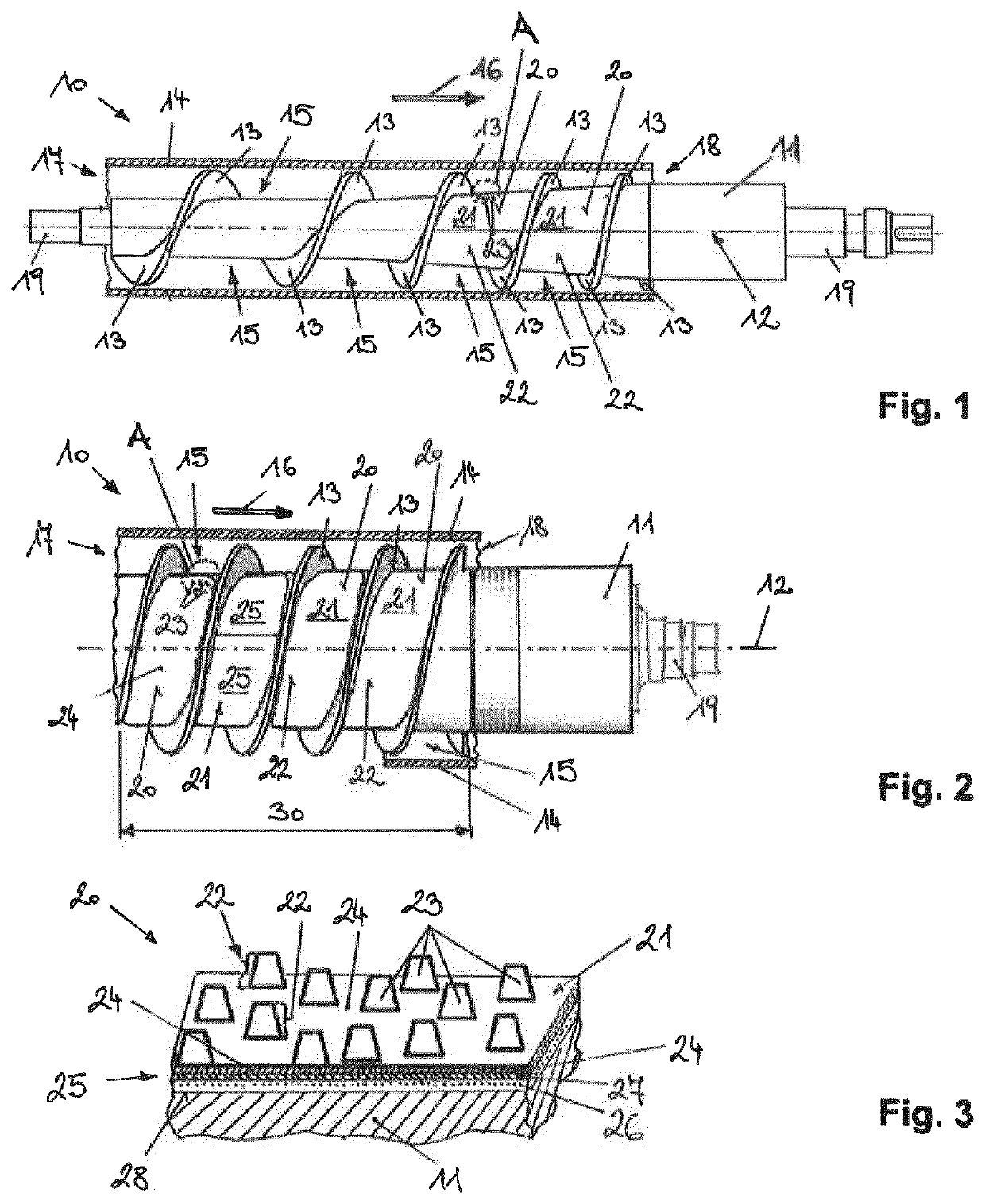
[0031]FIG. 1 shows a screw press 10 according to an embodiment of the invention, which comprises a screw shaft 11 with a screw shaft axis 12, where the screw shaft 11 has a spiral-shaped or helical conveying flight 13 that extends into the interior of an outer housing shell 14. A transport channel 15 is formed between the housing shell 14 and the screw shaft 11 and the conveying flight 13 mounted on it, respectively, through which the conveying material to be pressed is conveyed in a conveying direction 16 from an inlet port 17 in the housing shell 14 to an outlet port 18. By selecting suitable screw shaft 11 geometry that is designed such as to ascend conically in downstream conveying direction 16 towards the outlet port 18, for example, and choosing a suitable pitch for the conveying flight 13, a free cross-sectional area of the transport channel 15 is reduced successively in conveying direction 16.

[0032]The screw shaft 11 is supported rotatably in bearings (not shown) around the ...


PUM

PropertyMeasurementUnit
surface roughnessaaaaaaaaaa

Abstract

A screw press for separating off liquid from an article, comprising a screw shaft together with a conveying helix, which is arranged helically on the screw shaft, and a housing enclosure, which surrounds the conveying helix, wherein a transporting passage for the article which is to be conveyed is formed between the screw shaft, the conveying helix and the housing enclosure, wherein a composite comprising hard-material particles which are embedded in a matrix component to form surface roughness is fastened with material bonding to at least one surface portion of the screw shaft, within the transporting passage. A use of a composite comprising hard-material particles which are embedded in a uniformly distributed manner in a matrix component to form surface roughness, for the purpose of providing fastening with material bonding to at least one surface portion of a screw shaft.

Description

BACKGROUND[0001]The invention relates to a screw press for removing liquid from a material to be conveyed, comprising a screw shaft complete with a spiral-shaped conveying flight mounted on the screw shaft and a housing shell surrounding it, where a transport channel is formed for the material to be conveyed between the screw shaft, the conveying flight, and the housing shell. In addition, the use of a composite material is stated in the context of the invention in connection with a screw press.[0002]The conveying material to be processed by the screw press is usually a solid-liquid mixture, for example industrially produced chemical pulp fibers, from which the liquid carried along with the fibrous material is to be removed by pressing. Similarly, the conveying material to be compacted by the screw press can be pulp or sludge suspensions, waste paper, sawdust, or waste wood, for example.[0003]The principle of a screw press is sufficiently well known. A screw shaft fitted with a spir...

Claims


Application Information

Patent Timeline
Patent Type & Authority Patents(United States)
IPC IPC(8): B30B9/12B30B9/14
CPCB30B9/121B30B9/14B30B9/122B65G33/26B65G33/22B29C48/507B29C48/509B30B9/12B30B15/00
Inventor GHANIMI, YASSAR
Owner ANDRITZ AG
Learn More