Hot foil stamping device including a mobile window apparatus

a technology mobile window apparatus, which is applied in stamping, transfer printing, printing, etc., can solve the problems of potent risk and impair the quality of hot foil stamping, and achieve the effects of improving the safety of the device, high reliability of operation, and simple construction

Active Publication Date: 2021-07-06
BOBST SHANGHAI
View PDF12 Cites 0 Cited by
  • Summary
  • Abstract
  • Description
  • Claims
  • Application Information

AI Technical Summary

Benefits of technology

[0007]To overcome the existing deficiency in the hot foil stamping device, a mobile window apparatus for a hot foil stamping device, comprising: at least one first window portion, the first window portion movable in a first direction; at least one second window portion movable in a second direction different from the first direction; and an actuating means configured to move the first window and the second window, respectively; wherein said actuating means moves said first window portion and said second window portion between a closed position and an open position, in said open position, said first window portion and said second window portion being spaced apart from each other to form an access opening, and in said closed position, the first window portion and the second window portion are close to each other so as to substantially shield the access opening and to keep a gap between the first window portion and the second window portion for passing through a sheet material for processed.
[0017]When the hot foil stamping device adopts the mobile window apparatus according to the present invention, the window portions can substantially shield the access opening with only the small size of the gap is left, it is possible to avoid the presence of an opening area with potential safety hazard and improve the safety of the device when the horizontal foil conveying is used.
[0018]The preferred embodiment of the present invention employs a single actuating cylinder and a linkage mechanism comprised of cables and pulleys that are simple in construction and highly reliable in operation.

Problems solved by technology

However, when the horizontal foil conveying mode is selected, the window of the existing hot foil stamping device is moved upwardly to closed to a lower surface of the foil, and thus, a large open area is left above an upper surface of the foil, which renders a potential risk during production, and foreign objects may easily enter the operation area of the hot foil stamping device, which may impair a hot stamping quality.

Method used


Image

  • Hot foil stamping device including a mobile window apparatus
  • Hot foil stamping device including a mobile window apparatus
  • Hot foil stamping device including a mobile window apparatus

Examples


Embodiment Construction

[0035]Hereinafter, the present invention will be described further in conjunction with particular embodiments and accompanying drawings. More details are illustrated in the following description for sufficient understanding of the present invention, however, the present invention can be implemented in many other manners different from what is described here obviously. A person skilled in the art can make similar promotions and deductions without departing from the essence of the present invention as required and thus the protection scope of the present invention shall not be limited by the disclosure of these particular embodiments.

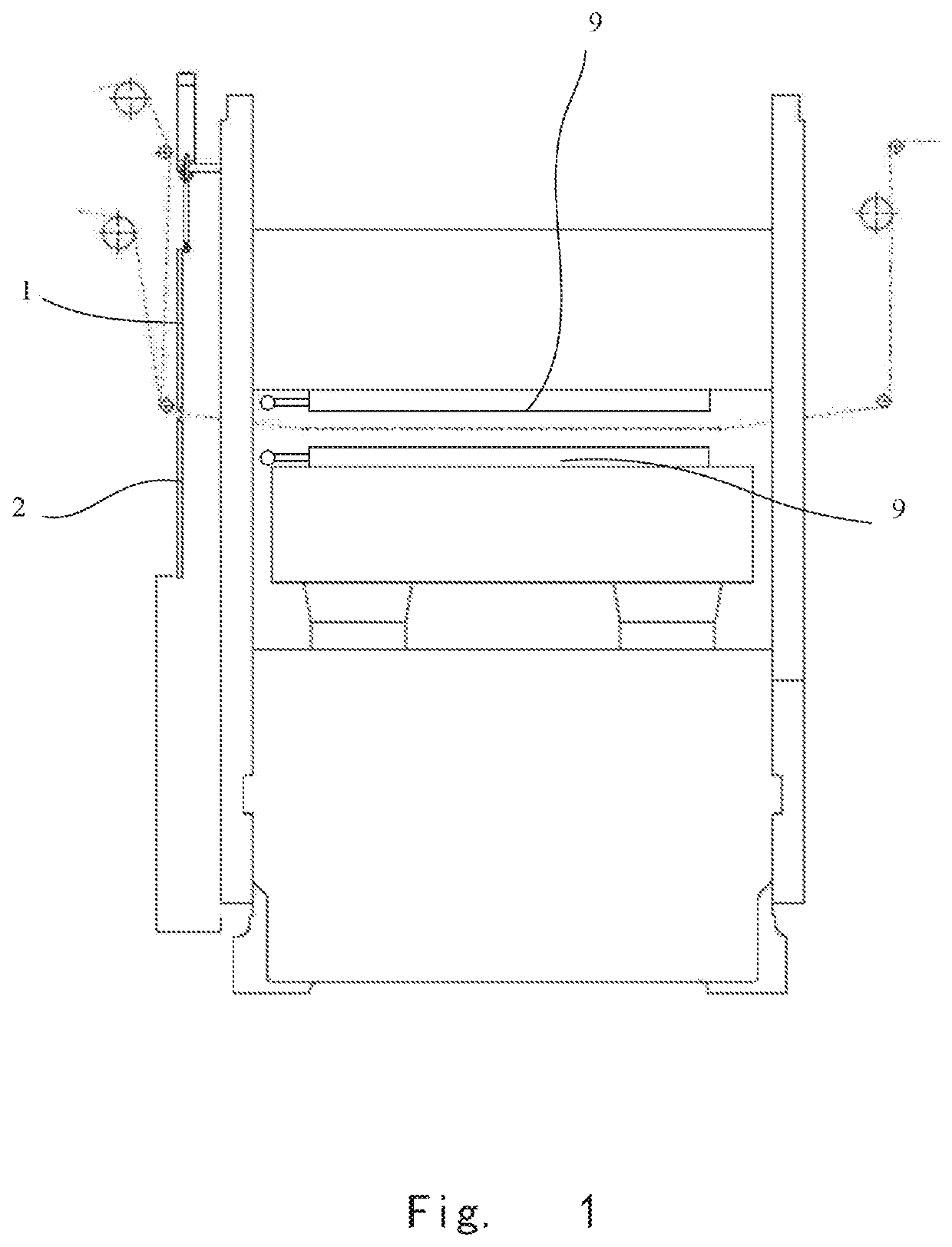
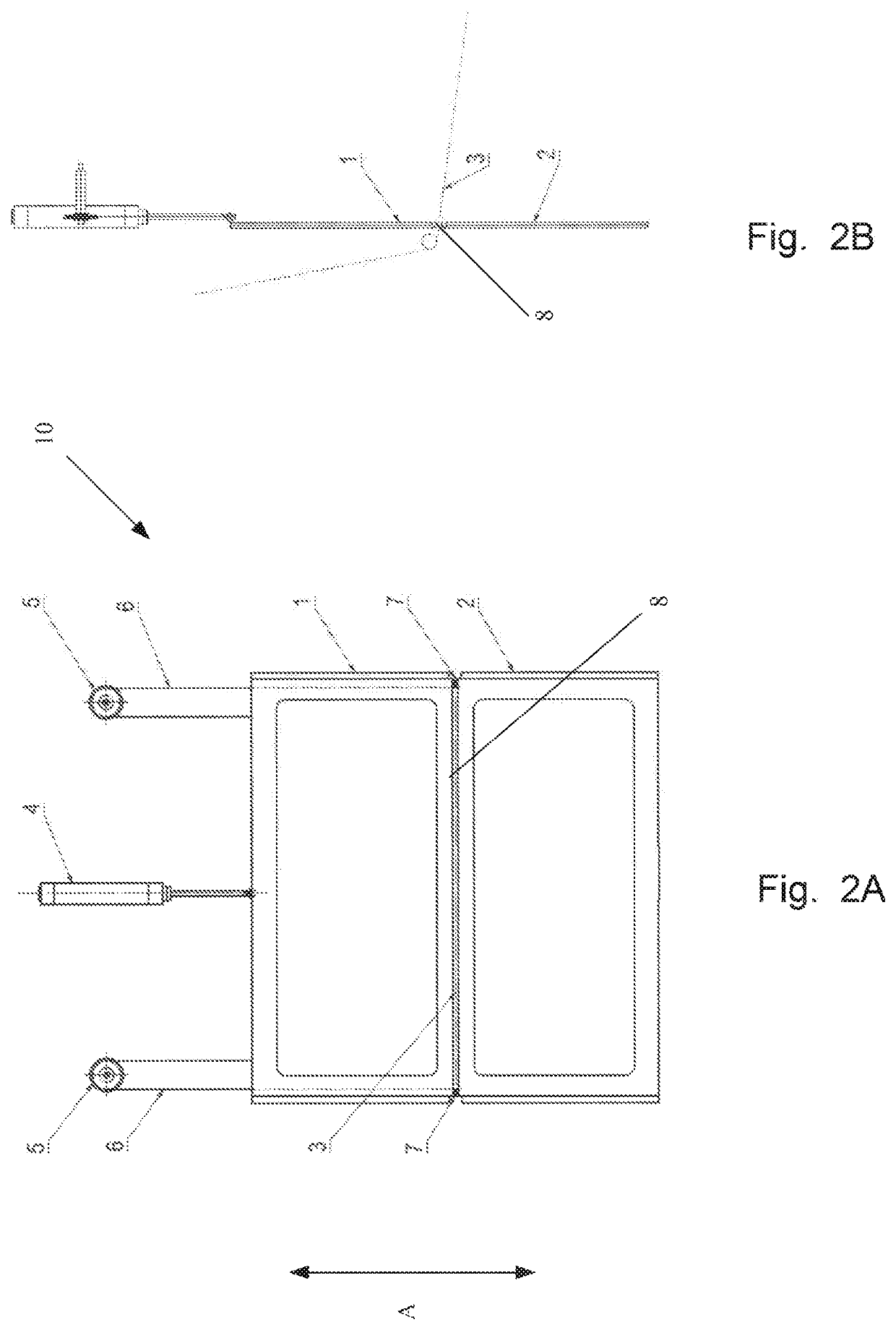
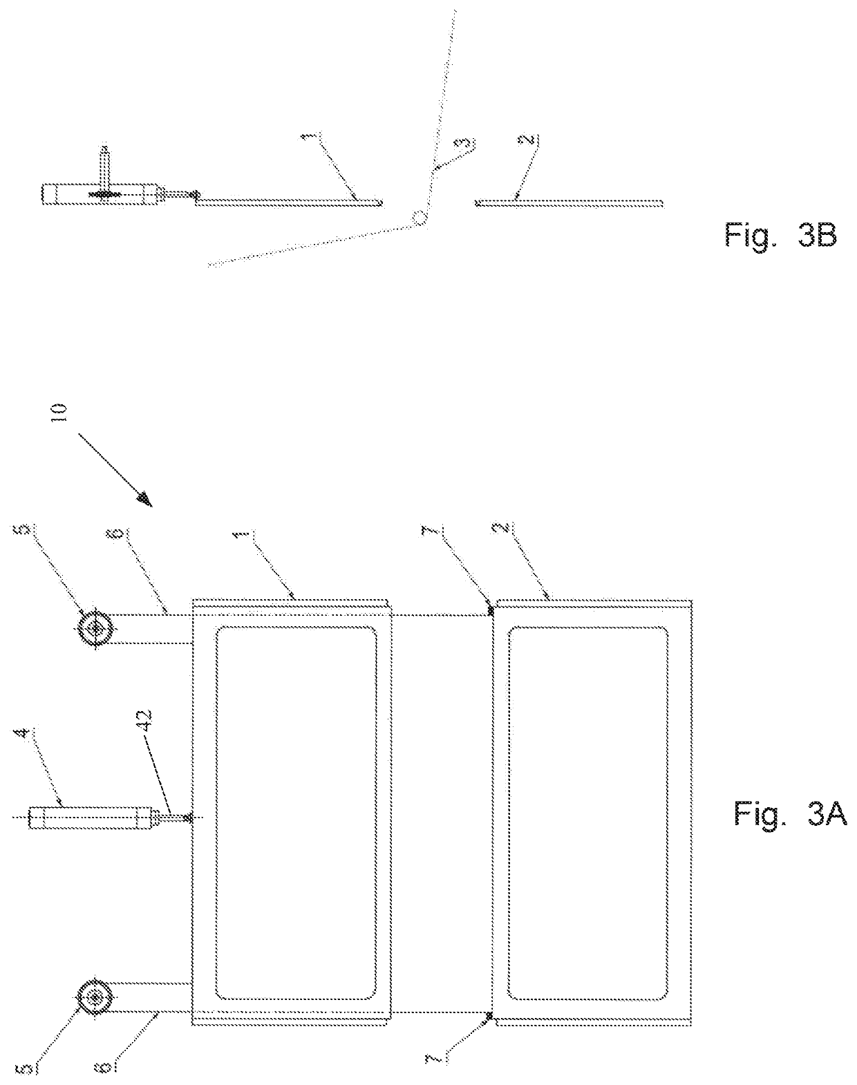
[0036]FIG. 1 is a schematic illustration of a hot foil stamping device with a mobile window apparatus 10 according to the invention, in which the foil material is conveyed with a horizontal foil conveying mode, i.e., the foil material passes horizontally between upper and lower platens and passes through a gap 8 between a first window portion 1 and a seco...


PUM


Abstract

The invention relates to a mobile window apparatus and a hot foil stamping device including the apparatus. The mobile window apparatus comprises at least one first window portion, the first window portion movable in a first direction; at least one second window portion movable in a second direction different from the first direction; and an actuating means configured to move the first window and the second window, respectively; wherein said actuating means moves said first window portion and said second window portion between a closed position and an open position, in said open position, said first window portion and said second window portion being spaced apart from each other to form an access opening, and in said closed position, the first window portion and the second window portion are close to each other so as to substantially shield the access opening and to keep a gap between the first window portion and the second window portion for passing through a sheet material for processed.

Description

CROSS-REFERENCE TO RELATED APPLICATION(S)[0001]This application claims the benefit of priority under 35 U.S.C. § 119 from Chinese Patent Application No. 201810239926.4, filed on Mar. 22, 2018, the contents of which is incorporated by reference in its entirety.TECHNICAL FIELD[0002]This invention relates to the field of packaging and printing, in particular to a hot foil stamping device with a mobile window apparatus.BACKGROUND OF INVENTION[0003]In the packaging industry, hot foil stamping devices are widely used. The conventional hot stamping device includes a transparent window, which can be opened for loading and unloading the molded board. During usage of the hot foil stamping device, the window is closed, so that an operation space is isolated from outside, which plays a protective role.[0004]There are two foil-conveying modes in a hot foil stamping device: a horizontal foil conveying mode and a longitudinal foil conveying mode. An operator of the device can choose a suitable mod...

Claims


Application Information

Patent Timeline
Patent Type & Authority Patents(United States)
IPC IPC(8): B41F1/60B41F13/00B44B5/00B41F16/00B41F33/00B41J29/12B41K3/66
CPCB41F13/0024B41F1/60B41F16/0046B41F33/0018B41J29/12B44B5/0052B41K3/66B41P2219/00B41P2233/20B41F19/06B41F16/00
Inventor YAN, ROY
Owner BOBST SHANGHAI
Why Eureka
Try Eureka