
Deflector structure for sunroof device

a technology for sunroofs and deflectors, which is applied in the direction of roofs, vehicle components, transportation and packaging, etc., can solve the problems of complex structure and reduce assembly productivity, and achieve the effect of simple structur

Active Publication Date: 2021-07-06
YACHIYO IND CO LTD
View PDF13 Cites 1 Cited by
  • Summary
  • Abstract
  • Description
  • Claims
  • Application Information

AI Technical Summary

Benefits of technology

The present invention is about a deflector structure for a sunroof device in a vehicle that prevents the arm from pivoting when the vehicle is traveling. This invention has a simple structure and inhibits the arm from being pivoted to ensure safety and comfort during travel.

Problems solved by technology

However, the related art described above has a structure to lock the spring by the locking lever for indirectly locking the arm portion being pivoted via the spring, to have problems of making the structure complicated and decreasing assembly productivity.

Method used


Image

  • Deflector structure for sunroof device
  • Deflector structure for sunroof device
  • Deflector structure for sunroof device

Examples


Embodiment Construction

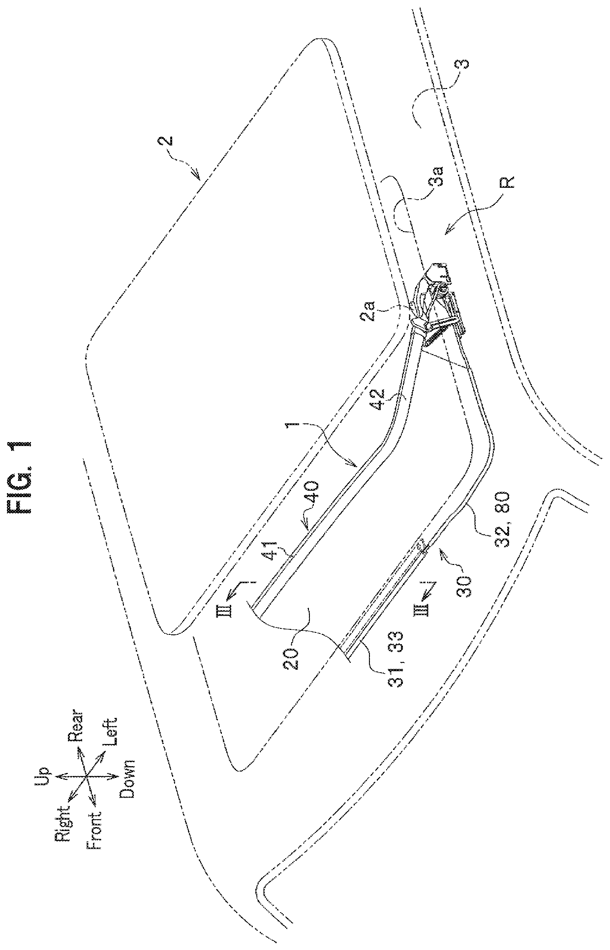
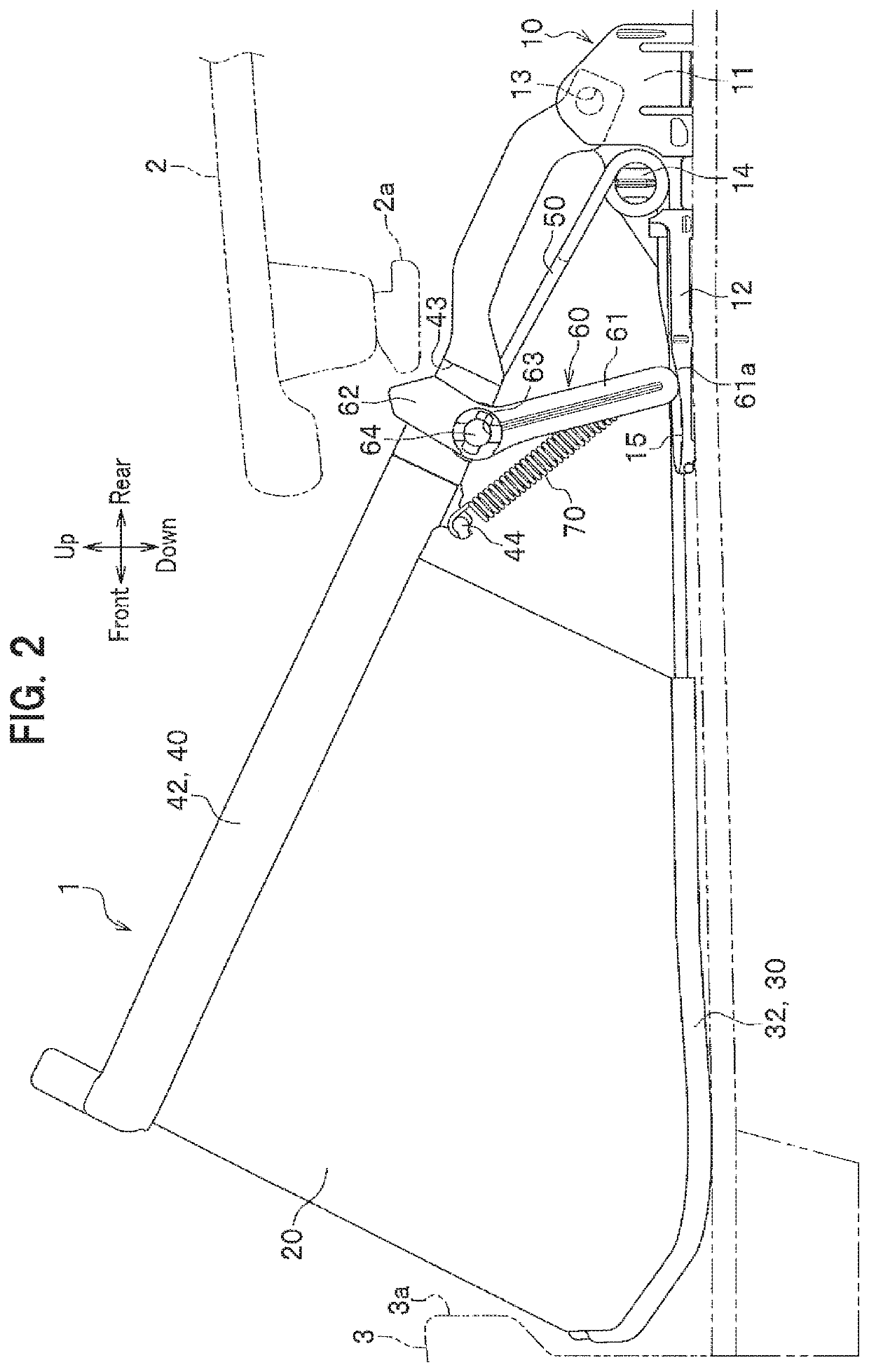
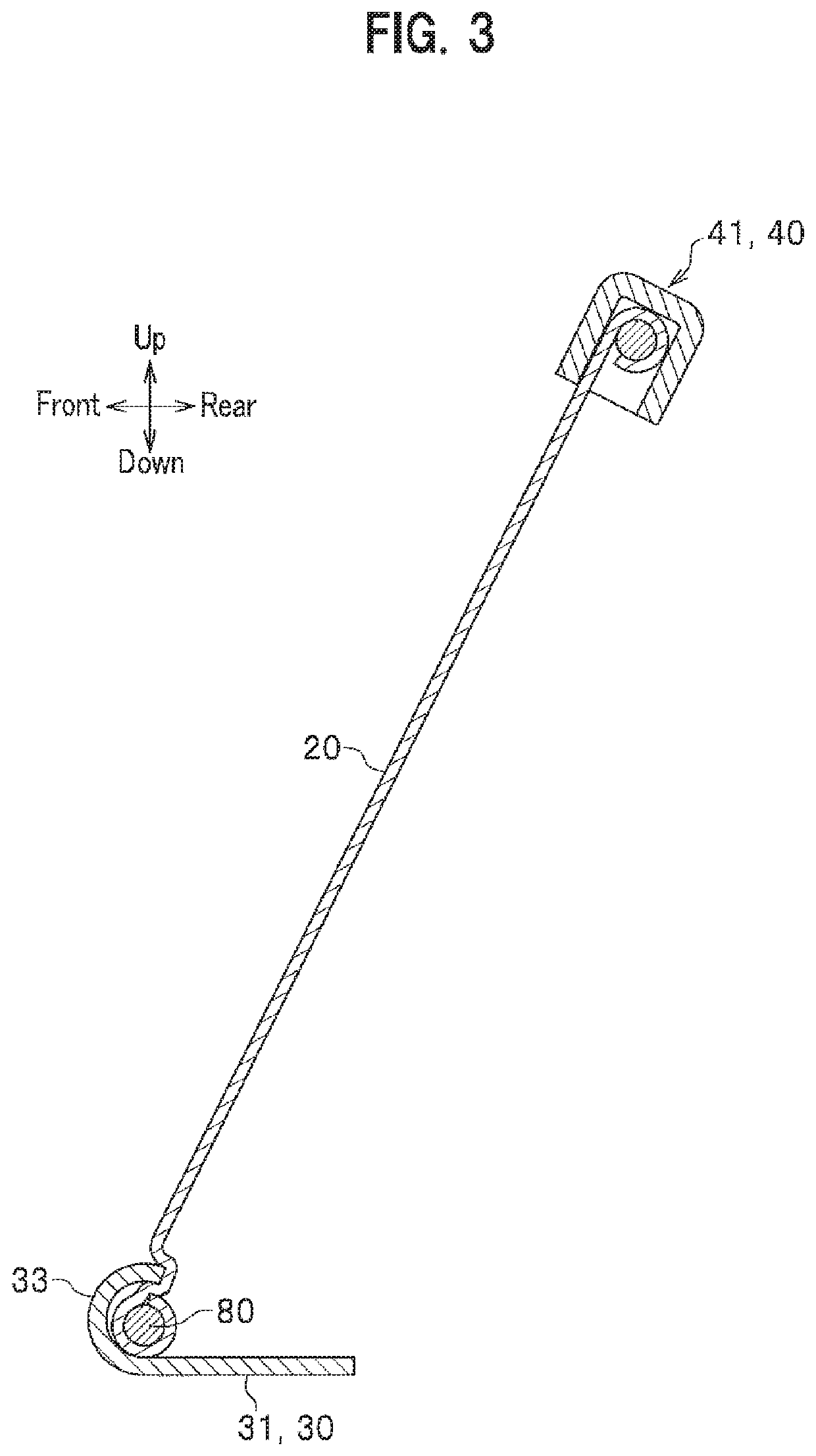
[0026]Embodiments of the present invention will be described in detail with reference to drawings. In the description, the same elements will be denoted by the same reference numerals and duplicate descriptions will be omitted. Directions of up and down, right and left, and front and rear in the description are based on up and down, right and left, and front and rear as viewed from the driver's seat, and a vehicle width direction is equal to a right-left direction. In FIG. 1, for the purpose of illustration, a deflector 1 is shown by solid lines and broken lines, while components other than the deflector 1 are shown by two-dot chain lines.

[0027]As shown in FIG. 1, a sunroof device R includes a roof panel 2 for covering and uncovering an opening 3a in a substantially rectangular shape formed in a fixed roof 3 of a vehicle body, and a deflector 1 projecting upward from the fixed roof 3 along a front edge of the opening 3a when the roof panel 2 slides rearward to uncover the opening 3a...


PUM


Abstract

Provided is a deflector structure for a sunroof device to inhibit an arm portion from being pivoted when a vehicle traveling, with a simple structure. The deflector structure includes: a fixed part fixed to a side frame; an affected part arranged anterior to the fixed part and affected by onrushing air; an arm portion having one end pivotally connected to the fixed part and the other end holding the affected part, and vertically pivoted about the fixed part; and a lock member having one end pivotally connected to the arm portion and the other end pivoted in conjunction with the arm portion being pivoted, wherein the lock member is configured such that a lock main body of the lock member is in contact with the fixed part and raised, at a predetermined pivot position, to lock the arm portion being pivoted downward.

Description

CROSS-REFERENCE TO RELATED APPLICATION[0001]This application is a U.S. National Stage Application under 35 U.S.C § 371 of International Patent Application No. PCT / JP2017 / 039525 filed on 1 Nov. 2017, which claims the benefit of priority to Japanese Patent Application No. 2016-228538 filed on 25 Nov. 2016, the disclosures of all of which are hereby incorporated by reference in their entireties.TECHNICAL FIELD[0002]The present invention relates to a deflector structure for a sunroof device.BACKGROUND ART[0003]A deflector structure for a sunroof device is widely known to include a net deflector (hereinafter referred to as an “affected part”) that is stretched out when in use to receive onrushing air, and is folded back and stored under the roof when not in use. Japanese Patent Application Publication No. 2016-60480, for example, discloses a deflector structure including an arm portion that holds an upper end portion of an affected part and is vertically pivoted, and a spring that biases...

Claims


Application Information

Patent Timeline
Patent Type & Authority Patents(United States)
IPC IPC(8): B60J7/22
CPCB60J7/22
Inventor NAKAMURA, TERUYUKIISHII, YOSHIYUKI
Owner YACHIYO IND CO LTD
Learn More