Pneumatic fender monitoring system

a technology of pneumatic fender and monitoring system, which is applied in the direction of instruments, vessels, apparatus for force/torque/work measurement, etc., can solve problems such as inability to determine, and achieve the effect of preventing damage to the pneumatic fender

Active Publication Date: 2021-07-06
THE YOKOHAMA RUBBER CO LTD
View PDF22 Cites 0 Cited by
  • Summary
  • Abstract
  • Description
  • Claims
  • Application Information

AI Technical Summary

Benefits of technology

[0004]The present technology provides a pneumatic fender monitoring system that can successively determine the state of the external shape of a pneumatic fender compressed and prevent damage.
[0006]According to an embodiment of the present technology, image data captured by using at least one of the front view imaging device that successively images the external shape in a front view of the pneumatic fender in use or the side view imaging device that successively images the external shape in a side view of the pneumatic fender in use is displayed on the monitor. Thus, the state of the external shape of the compressed pneumatic fender can be determined safely successively by using the image data displayed on the monitor. Additionally, the control unit determines, on the basis of the image data, whether the amount of deformation of the external shape of the pneumatic fender is within the preset tolerance range. Thus, appropriate measures can be taken on the basis of this determination to prevent damage to the pneumatic fender.

Problems solved by technology

Such a known monitoring system does not determine the state of the external shape of the pneumatic fender sandwiched between a vessel approaching a quay and the quay; or between two vessels and compressively deformed.
Accordingly, in a known monitoring system, it cannot be determined, for example, whether the pneumatic fender is sandwiched in an irregular state or whether the pneumatic fender is deformed in an abnormal manner and damaged.

Method used


Image

  • Pneumatic fender monitoring system
  • Pneumatic fender monitoring system
  • Pneumatic fender monitoring system

Examples


Embodiment Construction

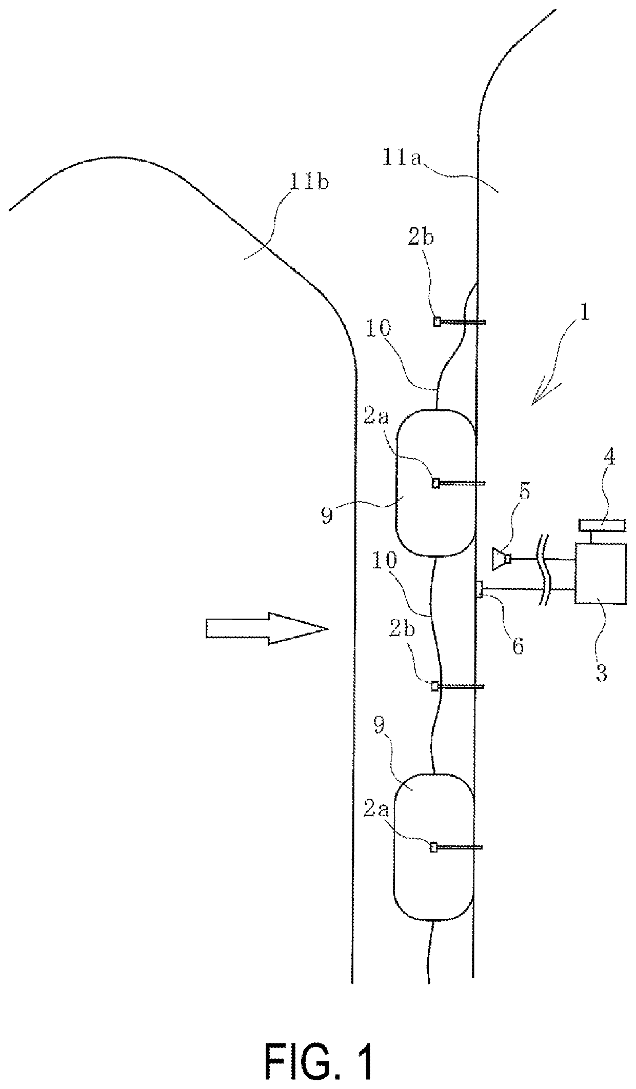
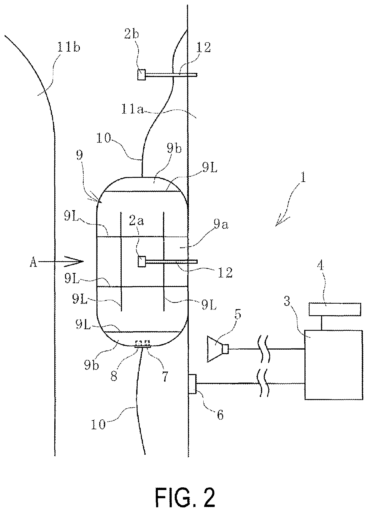
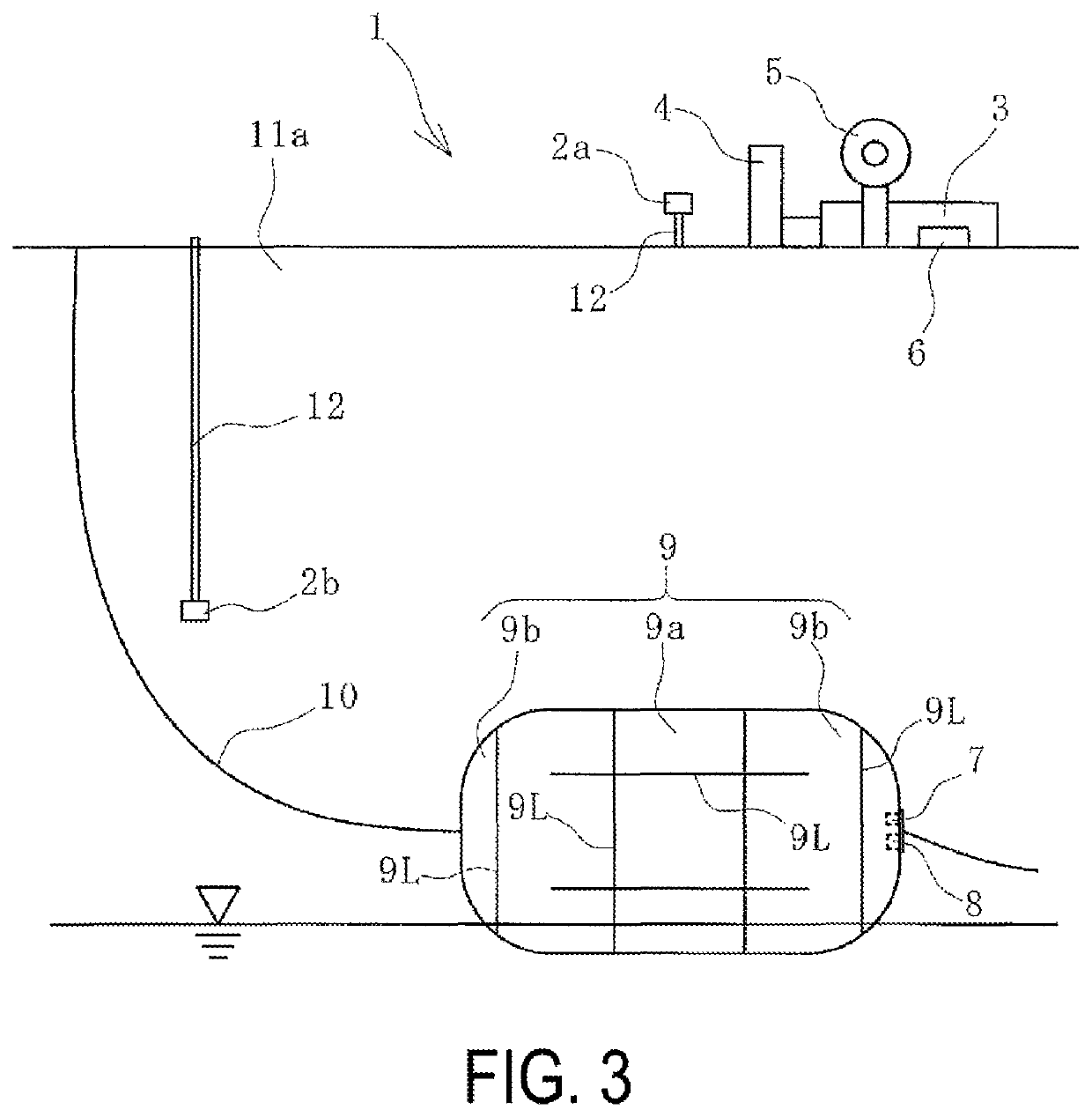
[0016]A pneumatic fender monitoring system according to embodiments of the present technology will be described below with reference to the drawings.

[0017]A pneumatic fender monitoring system 1 (hereinafter, referred to as a system 1) according to an embodiment of the present technology illustrated in FIGS. 1 to 3 can be applied to a pneumatic fender 9 (hereinafter, referred to as a fender 9) used at sea and the like. The fender 9 includes a cylindrical portion 9a and hemispherical portions 9b formed on both ends of the cylindrical portion 9a and connected to both the ends of the cylindrical portion 9a. The fender 9 may be used in a state of lying sideways, and the ends of the cylindrical portion 9a of the fender 9 may be disposed respectively on a left side and a right side. The fender 9 is used by being disposed between a vessel 11a and an object and used being sandwiched between the vessel 11a and the object. In the embodiment, the fender 9 is disposed between the vessel 11a and ...


PUM


Abstract

A pneumatic fender monitoring system is provided. Image data captured by using at least one of a front view imaging device that successively images an external shape in a front view of a pneumatic fender used disposed between a vessel and a vessel or a side view imaging device that successively images the external shape in a side view of the pneumatic fender is successively input into a control unit and successively displayed on a monitor, and the control unit determines, on the basis of the image data, whether an amount of deformation of the external shape of the pneumatic fender is within a preset tolerance range or outside of a preset tolerance range.

Description

TECHNICAL FIELD[0001]The present technology relates to a pneumatic fender monitoring system and particularly relates to a monitoring system that can successively determine the state of the external shape of a pneumatic fender compressed and prevent damage.BACKGROUND ART[0002]Various monitoring systems that monitor the state of a pneumatic fender are known (for example, see Japan Unexamined Patent Publication Nos. 2010-175298 and 2013-065352). Generally, in a known monitoring system, a meter such as a pressure gauge is disposed inside a fender, and the meter wirelessly sends detection data that is received by a receiver. Such a known monitoring system does not determine the state of the external shape of the pneumatic fender sandwiched between a vessel approaching a quay and the quay; or between two vessels and compressively deformed.[0003]Accordingly, in a known monitoring system, it cannot be determined, for example, whether the pneumatic fender is sandwiched in an irregular state ...

Claims


Application Information

Patent Timeline
Patent Type & Authority Patents(United States)
IPC IPC(8): B63B59/02E02B3/26B63B43/18E02B17/00
CPCE02B3/26B63B43/18B63B59/02E02B17/003B63B2059/025Y02A30/30H04N23/00G01B21/16G08B21/182G01L5/00G01K13/00
Inventor HOU, GANGMIYAMOTO, MASAHIKOTAKAHASHI, TAROMANISHI, MASAHARUTSUCHIYA, KOKO
Owner THE YOKOHAMA RUBBER CO LTD
Why Eureka
Try Eureka