
Process and apparatus for reducing NOx emissions

a technology of nox and process, applied in mechanical equipment, exhaust treatment, gas treatment, etc., can solve the problems of large scale, not over the full power range, so as to reduce nox emissions, increase the weight of the ship, and save valuable spa

Active Publication Date: 2021-07-13
KONINK DE VRIES SCHEEPSBOUW BV
View PDF10 Cites 0 Cited by
  • Summary
  • Abstract
  • Description
  • Claims
  • Application Information

AI Technical Summary

Benefits of technology

[0016]This process of the invention provides for a very efficient means of reducing NOx emission. The equipment for carrying out the process of the invention can be compact, so that it can be used on board without sacrificing too much valuable space and without increasing the weight of the ship too much.
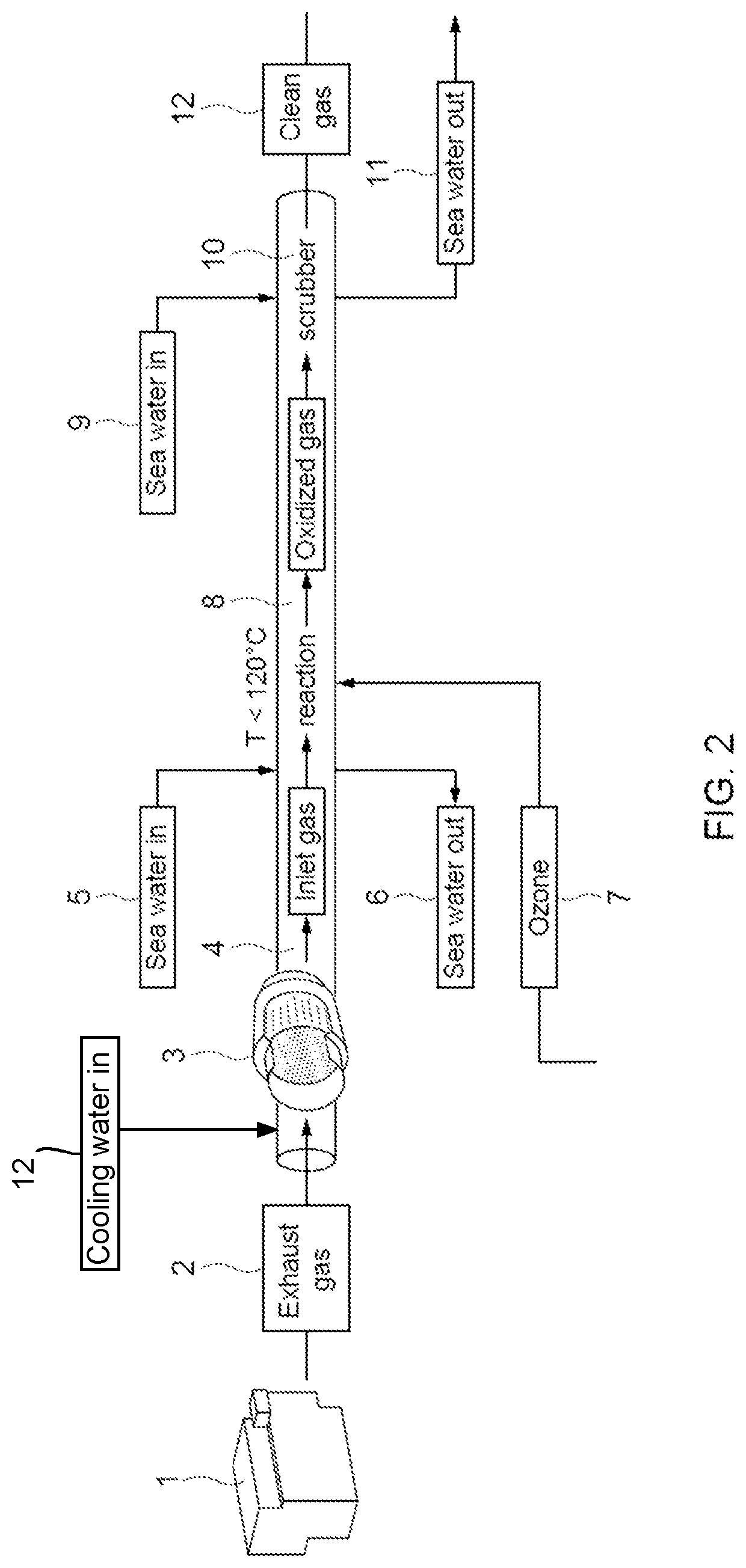
[0017]The present invention is based on the finding that by subjecting the NOx compounds present in the exhaust gas to an oxidation step, followed by contact with water, the oxidized compounds readily dissolve.

Problems solved by technology

NOx is produced during combustion, especially at high temperature and causes environmental problems, such as acid rain and photochemical smog.
Until now these known techniques have not been successfully applied, at least not on a large scale and not over the full power range, for the treatment of exhaust gases from marine engines, in particular from yacht engines.
Also these modified engines are not always suitable for use in yachts, in particular in view of the limited space for engines on board of these yachts.
Again this technique would be less desirable for luxury yachts since it would require large sacrifices of valuable space.
In addition, reducing agents such as urea need to be stocked in sufficient amounts, which increases the weight of the ship considerably and this results in higher emissions, including higher CO2 emissions, which is undesirable from an environmental point of view.
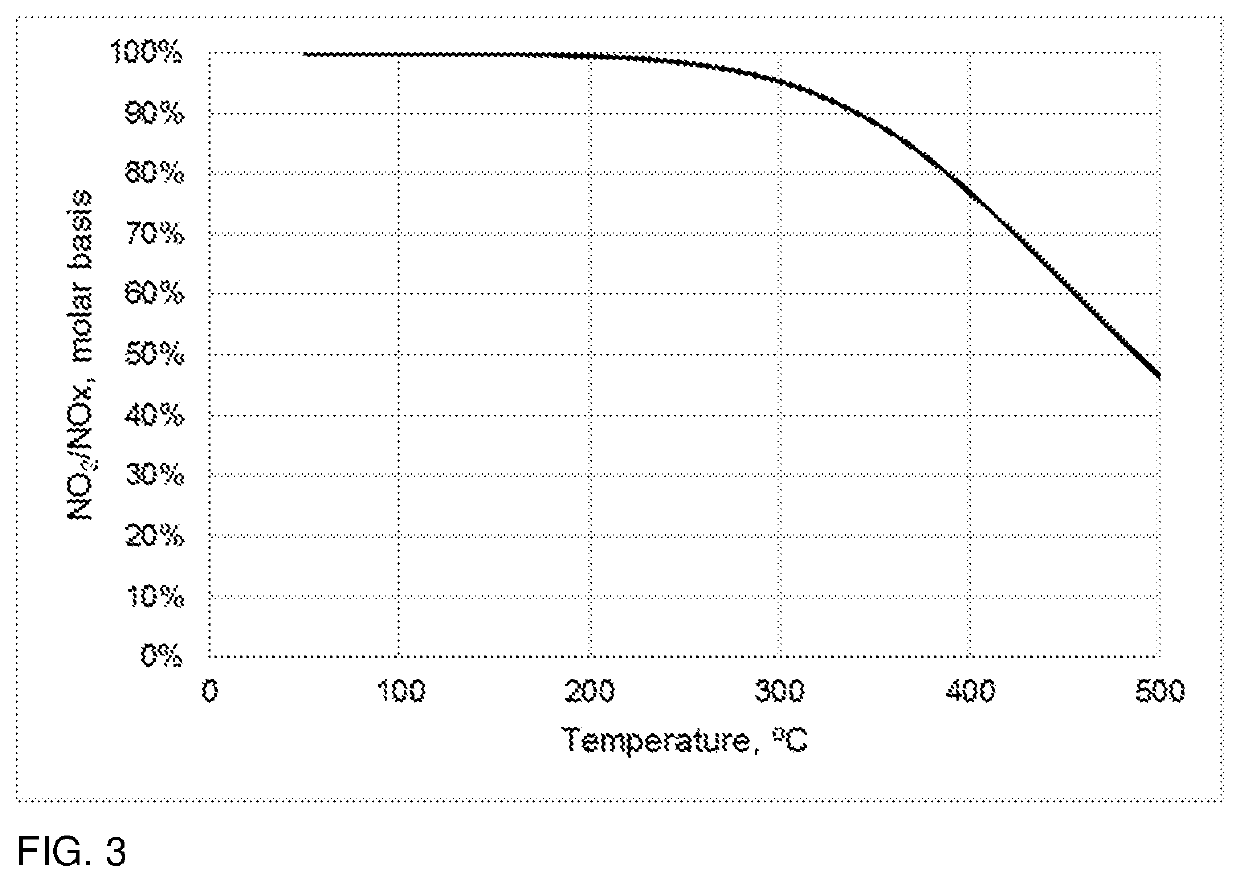
Furthermore, SCR techniques only work in a limited temperature range and are for instance not effective at lower temperatures, e.g. at temperatures below 250° C.

Method used


Image

  • Process and apparatus for reducing NOx emissions
  • Process and apparatus for reducing NOx emissions
  • Process and apparatus for reducing NOx emissions

Examples


example

[0051]A luxury yacht equipped with two diesel-fueled propulsion engines of 1140 kW is taken as an example. This yacht must comply with IMO tier III emission regulation, and emit a maximum of 2.06 g / kWh of NOx, which is currently only possible by using an SCR system. However, it should be noticed that the IMO test cycles cover the engine load range from 25% to 100%.

[0052]The SCR system is designed to work at exhaust gas temperatures above 250° C., which for the example vessel is achieved at engine loads above 10%. Therefore, the SCR system will be off (i.e., no urea will be injected) until the load reaches 10%, and the emissions from the engine will be uncontrolled, as can be seen in FIG. 4. When the temperature is above 250° C., urea is injected and the NOx emissions are regulated to a maximum of 1 g / kWh, according to the SCR system design.

[0053]In contrast, the system according to the invention can be used to control the NOx emissions to below 2 g / kWh in the full range of engine op...


PUM

PropertyMeasurementUnit
temperatureaaaaaaaaaa
temperaturesaaaaaaaaaa

Abstract

The invention is directed to a process and apparatus for treating an off-gas from a lean burn engine comprising contacting said off-gas with an oxidizing compound, thus producing oxidized NOx compounds, followed by contacting the oxidized NOx compounds with water, by which at least part of said oxidized NOx compounds dissolves in said water. The process of the invention provides for a very efficient means of reducing NOx emission. The equipment for carrying out the process of the invention can be compact, so that it can be used on board without sacrificing too much valuable space and without increasing the weight of the ship too much.

Description

RELATED APPLICATIONS[0001]This application is a National Stage Application under 35 U.S.C. 371 of co-pending PCT application PCT / NL2018 / 050352, filed May 30, 2018 and NL application no. 2018994, filed May 30, 2017 each of which are hereby incorporated by reference in their entireties.BACKGROUND OF THE INVENTION[0002]The invention is in the field of air pollution control. In particular the invention is in the field of the reduction of NOx emissions originating from marine engines, in particular lean burn engines, such as diesel-fueled engines as used in yachts, as well as in other ships.[0003]The term “NOx” is used for mono-nitrogen oxides, in practice mainly NO (nitric oxide) and NO2 (nitrogen dioxide). NOx is produced during combustion, especially at high temperature and causes environmental problems, such as acid rain and photochemical smog. In the past decades NOx emissions have been successfully reduced by various techniques. Until now these known techniques have not been succes...

Claims


Application Information

Patent Timeline
Patent Type & Authority Patents(United States)
IPC IPC(8): F01N3/00F01N3/20F01N13/00B01D53/56B01D53/94F01N3/08
CPCF01N3/2066F01N13/009B01D53/56B01D53/9418B01D2258/012F01N3/0814F01N2570/14F01N2610/02B01D53/78B01D53/8625B01D53/90F01N3/04F01N3/08F01N3/106B01D2251/104B01D2252/1035B01D2259/4566F01N2240/38F01N2590/02F01N2610/06Y02A50/20Y02T10/12
Inventor KOEVOET, JANWILLEGEN, JOOST VANDUYZER, JAN H.MORETZ-SOHN MONTEIRO, JULIANA GARCIA
Owner KONINK DE VRIES SCHEEPSBOUW BV
Learn More