Method and device in nodes with reduced signaling overhead used for wireless communication

a wireless communication and signaling overhead technology, applied in the direction of digital transmission, transmission path sub-channel allocation, wireless communication, etc., to achieve the effect of reducing signaling overhead, avoiding redundant blind detection, and streamlining operation

Active Publication Date: 2021-07-13
SHANGHAI LANGBO COMM TECH CO LTD
View PDF18 Cites 0 Cited by
  • Summary
  • Abstract
  • Description
  • Claims
  • Application Information

AI Technical Summary

Benefits of technology

[0011]In one embodiment, an advantage of the above method lies in that the time duration of the first time window and a type of multicarrier symbols comprised by the first time window are simultaneously indicated by a first signaling, thus reducing signaling overhead and simplifying the operation at the receiving side, and further avoiding excessive blind detection.
[0048]As described in the scheme of the present disclosure, for time domain resources located before the first shift point between uplink and downlink in the first time window, the first node does not need to perform detection on the target radio signal, instead, a direction blind detection on the control signaling will be sufficient to reduce the complexity of the reception of the first node; however, time domain resources located after the first shift point between uplink and downlink may comprise time domain resources configured to uplink by a transmitter of the first signaling, so that the transmitter of the first signaling cannot make sure of occupying the time domain resources, as a result, the first node is required to perform detection on the target radio signal to avoid unnecessary blind detection.

Problems solved by technology

As described in the scheme of the present disclosure, for time domain resources located before the first shift point between uplink and downlink in the first time window, the first node does not need to perform detection on the target radio signal, instead, a direction blind detection on the control signaling will be sufficient to reduce the complexity of the reception of the first node; however, time domain resources located after the first shift point between uplink and downlink may comprise time domain resources configured to uplink by a transmitter of the first signaling, so that the transmitter of the first signaling cannot make sure of occupying the time domain resources, as a result, the first node is required to perform detection on the target radio signal to avoid unnecessary blind detection.

Method used


Image

  • Method and device in nodes with reduced signaling overhead used for wireless communication
  • Method and device in nodes with reduced signaling overhead used for wireless communication
  • Method and device in nodes with reduced signaling overhead used for wireless communication

Examples


embodiment 1

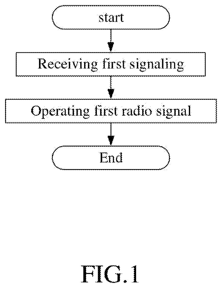
[0067]Embodiment 1 illustrates a flowchart of a first signaling, as shown in FIG. 1.

[0068]In Embodiment 1, the UE in the present disclosure first receives a first signaling; and then operates a first radio signal; the first signaling is a physical layer signaling, the first signaling comprises a first field and a second field; the first field indicates time duration of a first time window in time domain; the first time window comprises K first-type time units; a type of multicarrier symbols comprised by any of the K first-type time units is one of a first type, a second type and a third type; the K first-type time units include K1 first-type time unit(s); the second field is used for determining K1 type indicator set(s); the K1 type indicator set(s) is(are) respectively used for indicating a type(s) of multicarrier symbols comprised by the K1 first-type time unit(s); the operating is related to a type of multicarrier symbols occupied by the first radio signal; K is a positive intege...

embodiment 2

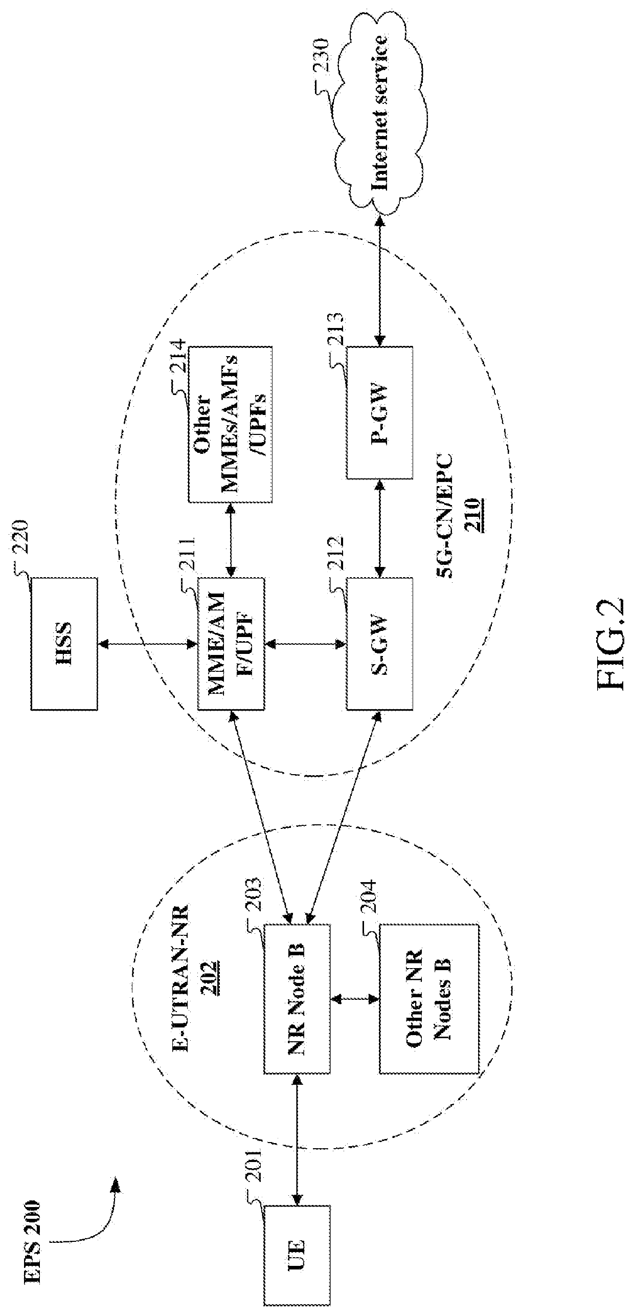
[0120]Embodiment 2 illustrates a schematic diagram of a network architecture, as shown in FIG. 2.

[0121]Embodiment 2 illustrates a schematic diagram of a network architecture according to the present disclosure, as shown in FIG. 2. FIG. 2 is a diagram illustrating a network architecture 200 of NR 5G, Long-Term Evolution (LTE) and Long-Term Evolution Advanced (LTE-A) systems. The NR 5G or LTE network architecture 200 may be called an Evolved Packet System (EPS) 200 or other applicable terminology. The EPS 200 may comprise one or more UEs 201, an NG-RAN 202, a 5G-Core / Network Evolved Packet Core (5G-CN / EPC) 210, a Home Subscriber Server (HSS) 220 and an Internet Service 230. The EPS 200 may be interconnected with other access networks. For simple description, the entities / interfaces are not shown. As shown in FIG. 2, the EPS 200 provides packet switching services. Those skilled in the art will find it easy to understand that various concepts presented throughout the present disclosure ...

embodiment 3

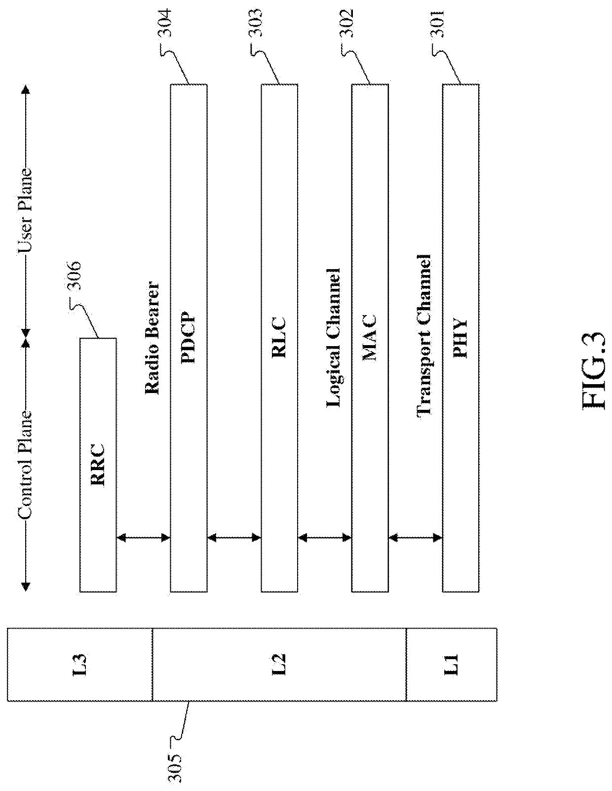
[0132]Embodiment 3 illustrates a schematic diagram of an example of a radio protocol architecture of a user plane and a control plane according to the present disclosure, as shown in FIG. 3.

[0133]FIG. 3 is a schematic diagram illustrating an embodiment of a radio protocol architecture of a user plane and a control plane. In FIG. 3, the radio protocol architecture for a UE and a base station (gNB or eNB) is represented by three layers, which are a layer 1, a layer 2 and a layer 3, respectively. The layer 1 (L1) is the lowest layer and performs signal processing functions of various PHY layers. The L1 is called PHY 301 in the present disclosure. The layer 2 (L2) 305 is above the PHY 301, and is in charge of the link between the UE and the gNB via the PHY 301. In the user plane, L2 305 comprises a Medium Access Control (MAC) sublayer 302, a Radio Link Control (RLC) sublayer 303 and a Packet Data Convergence Protocol (PDCP) sublayer 304. All the three sublayers terminate at the gNBs of ...


PUM


Abstract

The present disclosure provides a method and a device in nodes for wireless communication. A first node receives a first signaling, and operates a first radio signal; the first field indicates time duration of a first time window in time domain; the first time window comprises K first-type time units; a type of multicarrier symbols comprised by any of the K first-type time units is one of a first type, a second type and a third type; the K first-type time units include K1 first-type time unit(s); the second field is used for determining K1 type indication set(s), the K1 type indicating set(s) is(are) respectively used for indicating a type of multicarrier symbols comprised by the K1 first-type time unit(s). The present disclosure designs to create a connection between a first field and a second field, thus simplifying the indication of a slot format on unlicensed spectrum.

Description

CROSS-REFERENCE TO RELATED APPLICATION[0001]This application claims the priority benefit of Chinese Patent Application Serial Number 201811303959.7, filed on Nov. 3, 2018, the full disclosure of which is incorporated herein by reference.BACKGROUNDTechnical Field[0002]The present disclosure relates to transmission methods and devices in wireless communication systems, and in particular to a method and device of control signaling transmission.Related Art[0003]As future application scenarios of wireless communication systems become increasingly diversified, varying performance requirements have been posed on the systems. In order to meet such performance requirements of various application scenarios, a study item of access of unlicensed spectrum under New Radio (NR) has been approved at the 3rd Generation Partner Project (3GPP) Radio Access Network (RAN) #75 plenary session; at present, systems in Release 12, 13 and 14 are already able to support LBT-based wireless communication on unl...

Claims


Application Information

Patent Timeline
Patent Type & Authority Patents(United States)
IPC IPC(8): H04W72/04H04W16/14
CPCH04W72/042H04W16/14H04W72/044H04L27/2602H04W72/20H04W72/542H04W74/0808H04L5/0023H04L5/0048H04L5/0053H04L5/0091H04L5/0082H04W72/23
Inventor JIANG, QIWU, KEYINGZHANG, XIAOBO
Owner SHANGHAI LANGBO COMM TECH CO LTD
Why Eureka
Try Eureka