Method for operating a motor vehicle hydraulic brake system

a technology for hydraulic brakes and motor vehicles, applied in the direction of brake action initiations, foot actuation initiations, vehicle components, etc., can solve the problems of high braking pressure, insufficient maximum additional force to generate the desired braking force, and insufficient underpressure present in the brake booster to generate the desired braking pressur

Active Publication Date: 2021-07-20
FORD GLOBAL TECH LLC
View PDF10 Cites 0 Cited by
  • Summary
  • Abstract
  • Description
  • Claims
  • Application Information

AI Technical Summary

Benefits of technology

[0008]A method for operating a hydraulic brake system of a motor vehicle having a brake booster and a hydraulic brake boost comprising the steps of detecting a brake pressure and estimating an underpressure prevailing in an underpressure chamber of the brake booster based on the detected brake pressure and an actuation of the hydraulic brake boost. The method includes controlling the hydraulic brake boost based on the estimated underpressure.
[0016]Estimation faults of the consumption of the underpressure can be avoided. It possible, for example, to make use of information about the brake pedal travel, for example an estimation of the pedal travel, on the basis of the properties of the current actuation or of a preceding actuation of the HBB. A fixed value could also be assumed for the pedal travel, with the fixed value added at each HBB actuation operation to the pedal travel derived from the brake pressure, or the maximum possible pedal travel could be assumed. An improved estimation of the underpressure prevailing in the brake booster and therefore improved actuation or control of the hydraulic brake boosting operation can be achieved.
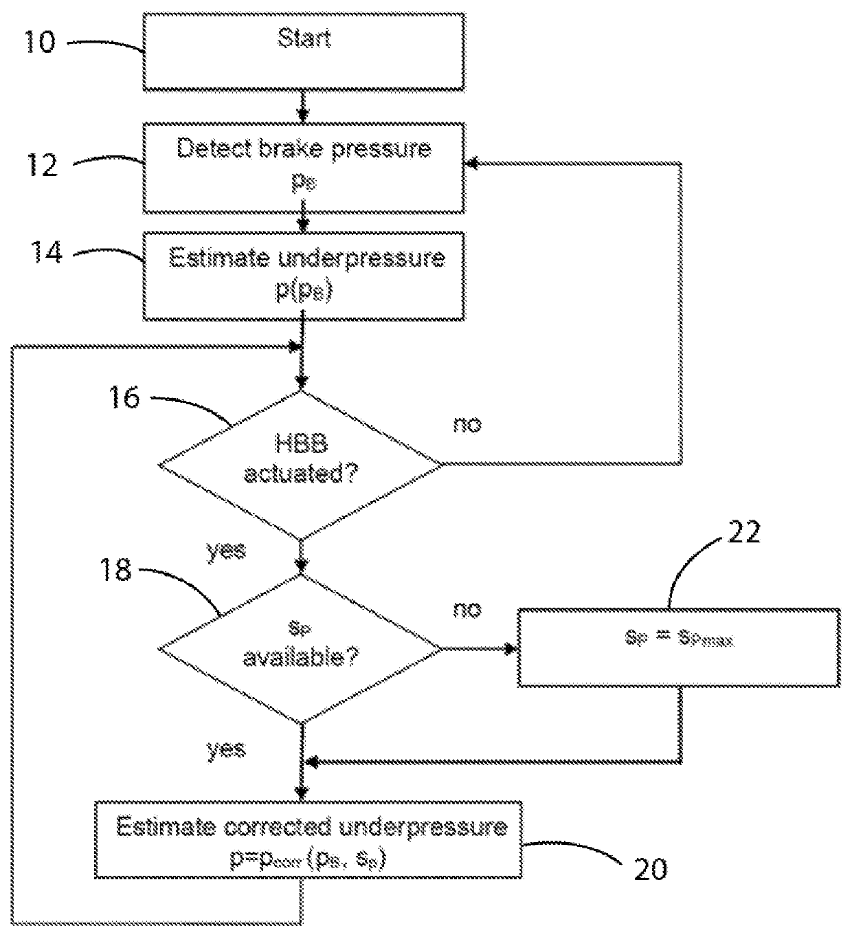
[0027]The detected brake pressure pB is, in particular, the hydraulic pressure prevailing in the master brake cylinder. The pressure can be detected, for example, with a pressure sensor arranged in a pressure chamber of the master brake cylinder or in a region of the fluid system of the brake system which is fluidically connected thereto. Simple and reliable detection of the brake pressure pB is made possible.
[0015]Depending on the instantaneous delivery capacity of the fluid pump, too little brake fluid may flow on from the brake fluid reservoir into the master brake cylinder. This leads to a situation in which although the measured brake pressure drops the brake pedal is depressed further with a constant applied pedal force. If the brake pedal is then released by the driver and as a result the HBB and the fluid pump are deactivated, the piston of the master brake cylinder is moved back and the position of the valve in the brake booster connects the working chamber to the underpressure chamber. This results in a drop in the underpressure reserve, a rise in the absolute pressure in the underpressure chamber. Owing to the actuation of the brake fluid pump by the HBB, the brake pedal has therefore been deflected further, which can bring about an increased consumption of underpressure when the brake pedal is released.
[0016]Estimation faults of the consumption of the underpressure can be avoided. It possible, for example, to make use of information about the brake pedal travel, for example an estimation of the pedal travel, on the basis of the properties of the current actuation or of a preceding actuation of the HBB. A fixed value could also be assumed for the pedal travel, with the fixed value added at each HBB actuation operation to the pedal travel derived from the brake pressure, or the maximum possible pedal travel could be assumed. An improved estimation of the underpressure prevailing in the brake booster and therefore improved actuation or control of the hydraulic brake boosting operation can be achieved.
[0030]In one embodiment, there may be provision wherein activation of the brake pedal is detected by detecting the brake pressure or the time profile thereof, that is the hydraulic pressure prevailing in the master brake cylinder. Since the brake pedal is connected to the master brake cylinder, the generated brake pressure depends on the brake pedal travel and permits it to be detected. Likewise, the number of activation operations of the brake pedal can be detected. In this way, an estimation of the underpressure p(pB) prevailing in the brake booster is made possible solely based on the brake pressure pB, detected by a pressure sensor assigned to the master brake cylinder.
[0016]Estimation faults of the consumption of the underpressure can be avoided. It possible, for example, to make use of information about the brake pedal travel, for example an estimation of the pedal travel, on the basis of the properties of the current actuation or of a preceding actuation of the HBB. A fixed value could also be assumed for the pedal travel, with the fixed value added at each HBB actuation operation to the pedal travel derived from the brake pressure, or the maximum possible pedal travel could be assumed. An improved estimation of the underpressure prevailing in the brake booster and therefore improved actuation or control of the hydraulic brake boosting operation can be achieved.
[0016]Estimation faults of the consumption of the underpressure can be avoided. It possible, for example, to make use of information about the brake pedal travel, for example an estimation of the pedal travel, on the basis of the properties of the current actuation or of a preceding actuation of the HBB. A fixed value could also be assumed for the pedal travel, with the fixed value added at each HBB actuation operation to the pedal travel derived from the brake pressure, or the maximum possible pedal travel could be assumed. An improved estimation of the underpressure prevailing in the brake booster and therefore improved actuation or control of the hydraulic brake boosting operation can be achieved.
[0034]In one embodiment, there may be provision wherein the hydraulic brake boosting function is actuated when a threshold value for the underpressure prevailing in the underpressure chamber of the brake booster or in the underpressure reservoir is undershot. This threshold value can, for example, be permanently predefinable or can depend on the respective situation, for example on the brake pedal travel. Intervention of the HBB for generating a braking force sufficient in the respective situation is easily made possible.

Problems solved by technology

When the motor vehicle is operating, situations can occur wherein the generated maximum additional force is not sufficient to generate the desired braking force.
For example, an emergency braking situation may require a high braking pressure and the underpressure present in the brake booster may not be sufficient to generate the desired braking pressure.
However, such a sensor causes increased expenditures in fabrication and maintenance.
Inaccuracies occur with known methods for estimating the underpressure prevailing in the brake booster, when the hydraulic brake boosting operation is actuated, because the measured brake pressure in the master brake cylinder does not permit clear conclusions to be drawn about the travel of the diaphragm in the brake booster when the hydraulic brake boosting operation is actuated.
In addition, actuating the hydraulic brake boosting operation may cause a drop in pressure in the master brake cylinder even though the wheel brake pressure acting in the wheel brake devices increases and the brake pedal is not released, but instead continues to be depressed by the driver.
In known methods, the decrease in the pressure in the master brake cylinder can be evaluated similarly to a release of the brake pedal, which gives rise to an incorrect estimation of the consumption of the underpressure and therefore to an incorrect estimation of the prevailing underpressure.
An incorrect estimation of the underpressure or of the underpressure reserve can have a disadvantageous effect on the functionality of the hydraulic brake boosting operation.

Method used


Image

  • Method for operating a motor vehicle hydraulic brake system

Examples


Embodiment Construction

[0012]The following description of the preferred embodiment(s) is merely exemplary in nature and is in no way intended to limit the invention, its application, or uses.

[0013]When the motor vehicle is operating and the driver activates the brake pedal and continuously increases the exerted brake pedal force, it results in an increase in the absolute air pressure in the working chamber caused by the changing position of the valve in the brake booster. This slightly reduces the underpressure prevailing in the underpressure chamber, i.e. the absolute pressure in the underpressure chamber increases slightly since the volume of the chamber shrinks because of the movement of the diaphragm while the number of air molecules initially remains the same.

[0014]If the increasing brake pressure exceeds a corresponding threshold value, the HBB actuates whereby a brake fluid pump of the vehicle movement dynamics control system pumps brake fluid from the master brake cylinder to the wheel brake cylin...


PUM


Abstract

A method for operating a hydraulic brake system of a motor vehicle having a brake booster and a hydraulic brake boost wherein a brake pressure is detected and an underpressure, prevailing in an underpressure chamber of the brake booster is estimated on the basis of the detected brake pressure. The hydraulic brake boost controlled based on the estimated underpressure, with the estimated underpressure taking into account an actuation of the hydraulic brake boost.

Description

CROSS-REFERENCE TO RELATED APPLICATIONS[0001]Not ApplicableBACKGROUND OF THE INVENTION1. Field of the Invention[0002]The invention relates to a method for operating a motor vehicle hydraulic brake system and, more particularly, for controlling a hydraulic brake booster.2. Description of Related Art[0003]Modern motor vehicles typically use a hydraulic brake system wherein a brake pedal activates a piston, connected to the brake pedal, of a master brake cylinder. The piston moves in a pressure chamber filled with brake fluid and generates a pressure, passed on via hydraulic lines, to at least one wheel brake device. The wheel brake device includes a wheel brake cylinder which, based on the pressure of the brake fluid, moves brake calipers with brake linings fitted thereon into abutment against a brake drum or a brake disk. The braking force acting on the wheel connected to the brake drum or brake disk generated and metered by activating the brake pedal. The master brake cylinder may b...

Claims


Application Information

Patent Timeline
Patent Type & Authority Patents(United States)
IPC IPC(8): B60T8/44B60T7/04B60T8/171B60T8/172B60T13/16B60T13/46
CPCB60T8/441B60T7/042B60T8/171B60T8/172B60T8/442B60T13/166B60T13/46B60T13/662
Inventor MOORE, IANSCHMALER, CHRISTIANBAUMANN, MATTHIASSVENSSON, THOMAS
Owner FORD GLOBAL TECH LLC
Why Eureka
Try Eureka