Double-acting friction stir spot welding method and apparatus

a friction stir and spot welding technology, applied in welding apparatus, metal-working equipment, manufacturing tools, etc., can solve the problems of deteriorating a manufacturing efficiency of the welded body, increasing the weight of the workpiece, etc., and achieve the effect of increasing the thickness of the build-up portion

Active Publication Date: 2021-08-10
KAWASAKI HEAVY IND LTD
View PDF33 Cites 2 Cited by
  • Summary
  • Abstract
  • Description
  • Claims
  • Application Information

AI Technical Summary

Benefits of technology

[0008]According to the method, the thickness dimension of the build-up portion can be further increased by using the additional material supplied to the concave portion of the backing portion.

Problems solved by technology

However, doing so either greatly increases a weight of the workpiece or requires the performance of a process to improve a fatigue strength of the welded portion.
Such actions lead to a deterioration in a manufacturing efficiency of the welded bodies.

Method used


Image

  • Double-acting friction stir spot welding method and apparatus
  • Double-acting friction stir spot welding method and apparatus
  • Double-acting friction stir spot welding method and apparatus

Examples


first embodiment

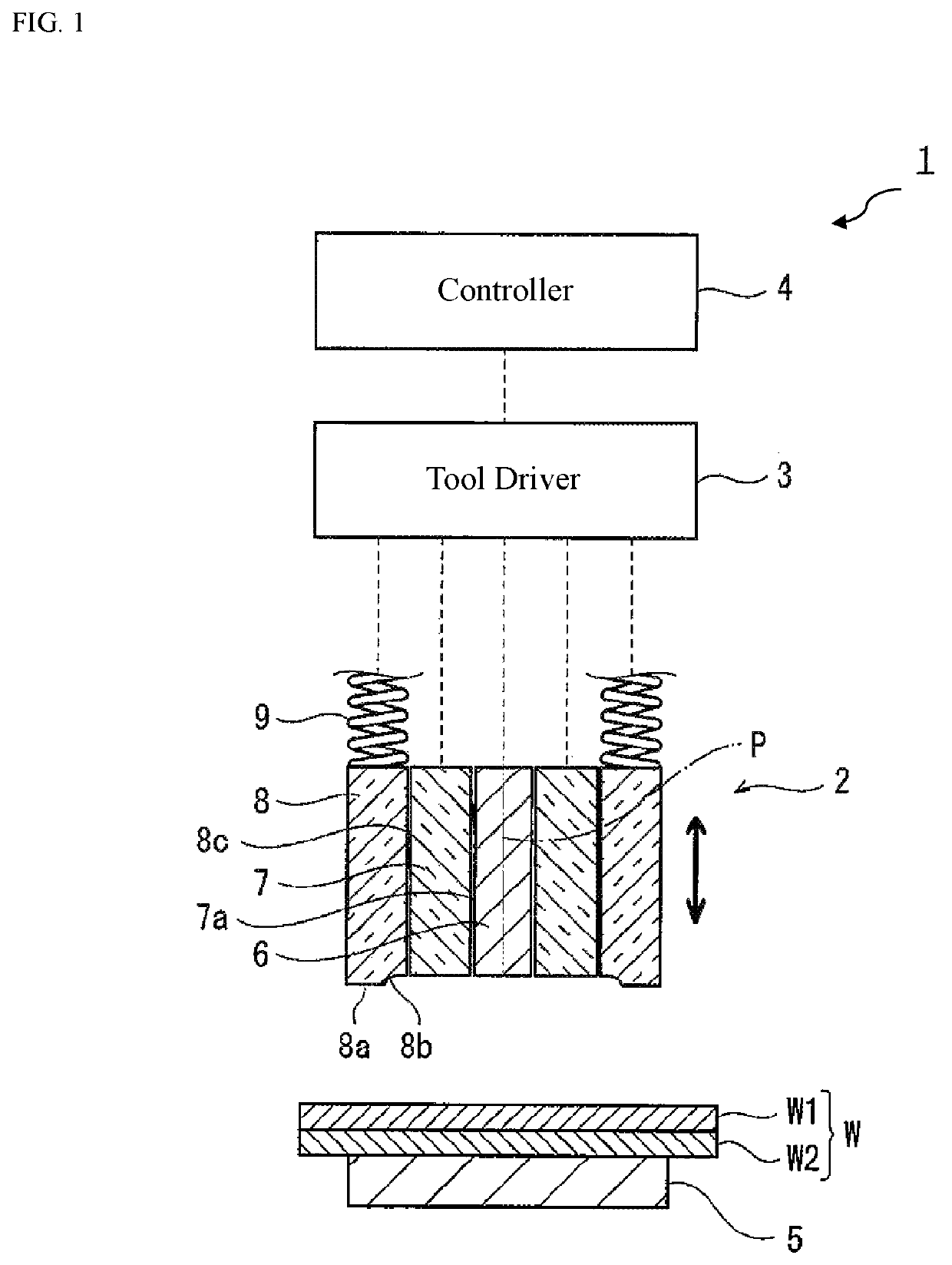
[0020]FIG. 1 shows a configuration of a main part of a double-acting friction stir spot welding device 1 (referred to as the device 1 hereinafter) according to the first embodiment. Referring to FIG. 1, a rotary tool 2 is shown in cross section, and a connection between the rotary tool 2 and a tool driver 3 is schematically indicated by broken lines.

[0021]The device 1 performs friction stir spot welding of workpieces W (for example, a pair of plate materials (a first plate material W1 and a second plate material W2)). The device 1 includes the rotary tool 2, the tool driver 3, a controller 4, a backing portion 5, and a clamp member 8.

[0022]The tool driver 3 moves the rotary tool 2 to a plurality of predetermined positions and drives the rotary tool 2 to rotate. The controller 4 controls the tool driver 3 so as to drive members 6 to 8 included in the rotary tool 2. The specific structure of the tool driver 3 is not limited, and for example, a known structure can be used.

[0023]The con...

second embodiment

[0076]FIG. 7 illustrates a view showing the configuration of the main part of a double-acting friction stir spot welding device according to the second embodiment. This embodiment differs from the first embodiment in that a backing portion 15 has a concave portion 15a formed in the surface facing the workpiece W so as to be recessed in the axis P direction. The concave portion 15a is provided at a position facing a chamber portion 8b with a workpiece W interposed between them, and extends along the surface of the workpiece W.

[0077]For example, the concave portion 15a has a peripheral edge having a circuit shape when viewed in a front view (viewed in the axis P direction). The concave portion 15a has an inclined surface whose inner diameter gradually decreases from the peripheral edge toward the inside of the backing portion 15 in the axis P direction and a bottom surface surrounded by the inclined surface. The inner diameter of the peripheral edge of the concave portion 15a can be s...


PUM

PropertyMeasurementUnit
diameteraaaaaaaaaa
plastic flowaaaaaaaaaa
inner diameteraaaaaaaaaa

Abstract

A friction stir spot welding method includes a welding step of forming a build-up portion on a workpiece by friction-stirring the workpiece, using a pin and a shoulder, while pressing a surface of the workpiece with an end face of a clamp, and filling a portion of the workpiece being softened in a chamber portion of the clamp by press-fitting at least one of the pin and the shoulder into a plastic flow portion of the workpiece. and the friction stir spot welding method further includes a pressing step of pressing a surface of at least one of a region of the build-up portion, which is frictionally stirred by the shoulder, and an adjacent region of the build-up portion against the end face of the clamp with the pin and the shoulder retracted into an accommodation space.

Description

CROSS-REFERENCES TO RELATED APPLICATIONS[0001]The present application is a bypass continuation of PCT Application No. PCT / JP2018 / 032886, filed Sep. 5, 2018, which claims priority to JP 2017-172969, filed Sep. 8, 2017, both of which are incorporated herein by reference.TECHNICAL FIELD[0002]The present application relates to a double-acting friction stir spot welding method, and more particularly, to a technique for improving a fatigue strength of a joint portion formed by welding.BACKGROUND ART[0003]Conventionally, a double-acting friction stir spot welding device is provided with a pin member and a shoulder member that can rotate around a predetermined axis independently of each other and advance and retract in an axial direction. The double-action friction stir spot welding device is further provided with a clamp member that surrounds an outer periphery of the shoulder member to advance and retract in the axial direction.[0004]In welding a workpiece by friction stir spot welding, i...

Claims


Application Information

Patent Timeline
Patent Type & Authority Patents(United States)
IPC IPC(8): B23K20/12
CPCB23K20/126B23K20/1225B23K20/122B23K20/1255B23K20/1265
Inventor HIRANO, MASAAKIYAMADA, ETSUKO
Owner KAWASAKI HEAVY IND LTD
Why Eureka
Try Eureka