
Infrared spectrophotometer

a spectrophotometer and infrared technology, applied in the field of optical sensors, can solve the problems of limiting the uptake of commercial and consumer applications, consuming a lot of power, and expensive ir systems

Active Publication Date: 2021-08-17
UNIVERSITY OF THE WEST OF SCOTLAND
View PDF47 Cites 3 Cited by
  • Summary
  • Abstract
  • Description
  • Claims
  • Application Information

AI Technical Summary

Benefits of technology

[0019]In use, the sensor typically detects light which is transmitted through the at least one interference filter and / or light which is reflected by the at least one interference filter. Assuming that both absorption and scattering of incident light by the at least one interference filter are negligible, the intensity of light received by the plurality of light detectors is dependent on both the spatial and spectral variations in the intensity of light incident on the at least one interference filter, as well as the spectral variation in the light transmitted and / or reflected by the at least one interference filter. By compensating measurements of the reflected and / or transmitted light intensity for the spatial variation in the intensity of light incident on the at least one interference filter, the spectral variation of the light intensity can be isolated, resulting in a more accurate measurement of the absorption spectra at each detector location. The sensor can therefore correct for the non-uniformity of illumination across the at least one interference filter (and therefore across the plurality of light detectors).
[0115]The at least one interference filter (or each of the plurality of interference filters) may be a high-pass filter. The high-pass filter is typically an edge filter having a (i.e. relatively) steep lower band edge. The high-pass filter permits all of the light to be used, while the steep lower band edge permits accurate deconvolution of the spectral content of a received signal.

Problems solved by technology

IR spectroscopic techniques can be sensitive and accurate, but current IR systems are often expensive and relatively large, and can consume a lot of power, limiting uptake in commercial and consumer applications.
Individual NDIR sensors are not generally suitable for detecting two or more species simultaneously; multiple NDIR sensors are required for such purposes.

Method used


Image

  • Infrared spectrophotometer
  • Infrared spectrophotometer
  • Infrared spectrophotometer

Examples


Embodiment Construction

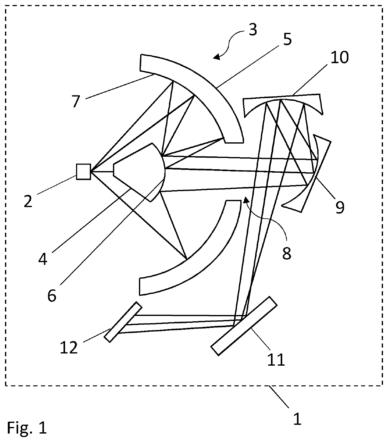
[0181]FIG. 1 shows the optical configuration of a multispectral sensor 1. Although the sensor may be used to detect analytes in a sample of any light-permeable fluid such as a gas or a liquid, this example embodiment focuses on the detection of analytes in a gas sample.

[0182]The sensor has a broadband infrared light source consisting of a MEMS hotplate 2. The hotplate 2 is configured to emit infrared light having wavelengths in the range 2000 nm to 14000 nm. The hotplate comprises a linear array of light-emitting hotspots which are formed by current density focusing due to a periodic spatial variation in the resistance of the hotplate. The output from the MEMS hotplate 2 can be modulated (for example pulse-wave modulated).

[0183]A reflective collector 3 consists of a first reflector 4 and a second reflector 5. Both first and second reflectors 4 and 5 are formed from injection moulded plastics materials coated with gold. The first reflector 4 has a substantially hemispherical, convex ...


PUM

PropertyMeasurementUnit
wavelengthsaaaaaaaaaa

Abstract

An optical sensor for multispectral analysis of a fluid sample comprises at least one light source, at least one interference filter, and a plurality of light detectors arranged such that light emitted by the at least one light source is incident on the at least one interference filter. There is a spatial variation in the intensity of light incident on the said at least one interference filter.

Description

FIELD OF THE INVENTION[0001]The invention relates to optical sensors and methods for detecting one or more species in a fluid sample, and methods for calibrating optical sensors.BACKGROUND TO THE INVENTION[0002]The detection of species (such as atoms, molecules, molecular fragments or ions) in fluid samples (such as gas or liquid samples) is necessary in many fields of technology, including industrial safety monitoring, medicine, food processing and environmental monitoring. Sensors currently used include electrochemical sensors, catalytic sensors, photoionisation sensors and spectroscopic sensors.[0003]Infrared (IR) spectroscopic techniques generally involve illuminating a gas or liquid sample with infrared light in order to excite atomic and / or molecular vibrations and studying the resulting spectrum of light absorbed by or transmitted through the sample in order to identify the vibrations. IR spectroscopic techniques can be sensitive and accurate, but current IR systems are often...

Claims


Application Information

Patent Timeline
Patent Type & Authority Patents(United States)
IPC IPC(8): G01J3/10G01J3/02G01J3/12G01J3/42G01N21/3504G01N21/3577
CPCG01J3/108G01J3/0208G01J3/12G01J3/42G01J2003/1226G01N21/3504G01N21/3577G01N21/27G01N21/359
Inventor WADDELL, EWANGIBSON, DESMOND
Owner UNIVERSITY OF THE WEST OF SCOTLAND
Learn More