
Cylinder head with connected exhaust manifold of an internal combustion engine

a technology of connected exhaust manifold and internal combustion engine, which is applied in the direction of engine components, sealing arrangements, and silting apparatus, etc., can solve the problems of inability to meet the requirements of the customer, etc., to achieve low cost, reduce thermal load, and simple

Active Publication Date: 2021-08-31
MAN TRUCK & BUS AG
View PDF21 Cites 0 Cited by
  • Summary
  • Abstract
  • Description
  • Claims
  • Application Information

AI Technical Summary

Benefits of technology

This patent is about a way to reduce the heat in the exhaust duct of an engine and to make it easier to seal the exhaust manifold. It does this by using a simple and low-cost solution. The flange bushing insert is made of a single component that has two functions: it insulates the exhaust duct and seals the exhaust manifold. This design helps to reduce the amount of heat released, which can lower the need for a cooling system and increase energy conversion in the engine. The flange part fixes the bushing in place, ensuring it stays stable and secure. Overall, this solution is cost-effective and efficient for reducing heat and improving performance.

Problems solved by technology

As a result, components close to the exhaust duct can be loaded in a thermally inadmissible manner and possibly damaged.
These are clearly disadvantageously complex, costly solutions.

Method used


Image

  • Cylinder head with connected exhaust manifold of an internal combustion engine

Examples


Embodiment Construction

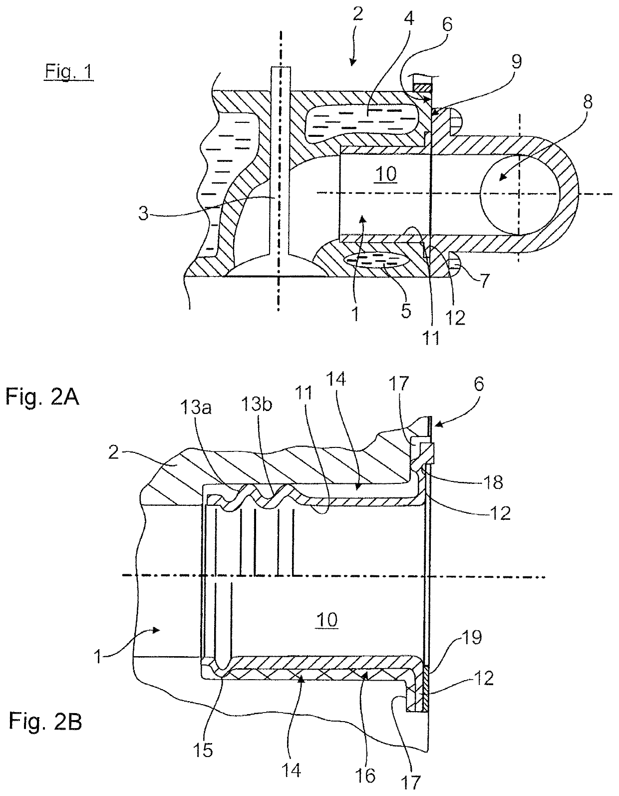
[0023]A longitudinal section through an exhaust duct 1 of a cylinder head 2 of an internal combustion engine is represented in FIG. 1. Exhaust duct 1 lies on the outflow side downstream of an outlet valve 3 and is partially surrounded by cooling ducts 4, 5 through which cooling medium flows.

[0024]Exhaust duct 1 ends at an outer cylinder head connecting face 6, to which here, by way of example by several screw connections or screw joints 7, an exhaust manifold 8 is connected in an exhaust gas-impervious manner with its assigned exhaust manifold connecting face 9.

[0025]A flange bushing insert 10, which is represented in an enlarged form with further details in FIGS. 2a and 2b, is inserted into exhaust duct 1 in a linear region:

[0026]Here, flange bushing insert 10 is constructed from a bushing part 11 and an end-side flange part 12.

[0027]In a first embodiment according to FIG. 2a (upper region of FIG. 2), bushing part 11 has, opposite flange part 12, two beads 13a, 13b lying next to on...


PUM


Abstract

A cylinder head with connected exhaust manifold of an internal combustion engine the cylinder head has an exhaust duct ending at a cylinder head connecting face to which the exhaust manifold is connected. A flange bushing insert having a bushing part and an end-side flange, is inserted into an exhaust gas duct of the cylinder head. The bushing part has a radially protruding, circumferential bead as a spacer and sealing element that bears against the exhaust duct inner wall. The flange projects at the end of the flange bushing insert and is clamped between the cylinder head connecting face and the exhaust manifold connecting face such that a circumferential insulating gap.

Description

BACKGROUND OF THE INVENTION1. Field of the Invention[0001]The invention relates to a cylinder head with connected exhaust manifold of an internal combustion engine.2. Description of the Related Art[0002]In one generally known arrangement, the cylinder head has, after the outlet valve, an exhaust duct that ends on an outer cylinder head connecting face. An exhaust manifold with an assigned exhaust manifold connecting face is connected by a screw joint to this cylinder head connecting face such that the exhaust duct of the cylinder head is continued in the exhaust manifold.[0003]An exhaust manifold seal is fitted between the cylinder head connecting face and the exhaust manifold connecting face for an exhaust gas-impervious connection of the exhaust manifold to the cylinder head. Coolant ducts through which a coolant flows in the cylinder head lie in the region of the exhaust duct. Depending on the number of cylinders of the internal combustion engine and their arrangement, a cylinder...

Claims


Application Information

Patent Timeline
Patent Type & Authority Patents(United States)
IPC IPC(8): F02F1/42F01N13/10F02F11/00F02F1/00
CPCF02F1/4264F01N13/102F02F1/4271F02F11/002F02F2001/008F01N13/105
Inventor HOLLWECK, JOHANNESBOEHME, ULRICHBÖTTCHER, TOBIAS ARROYO
Owner MAN TRUCK & BUS AG
Learn More