CATV device with resistive signal distribution network

a resistive signal and catv technology, applied in the field of radio frequency (“ rf”) signal amplifiers, can solve the problems of occupying significant area on the printed circuit board, relatively expensive passive devices such as power dividers, and relatively expensive elements, so as to reduce surface area requirements, increase volume, and reduce surface area

Active Publication Date: 2021-08-31
DIGICOMM INT LLC
View PDF56 Cites 0 Cited by
  • Summary
  • Abstract
  • Description
  • Claims
  • Application Information

AI Technical Summary

Benefits of technology

[0027]The Applicant has appreciated a replacement for the ferrite-based power dividers, which replacement has many advantages and, on balance, leads to an improved RF signal amplifier. The Applicant has configured a resistive splitter network for the active output ports of the RF signal amplifier. The resistors have numerous advantages over the ferrite core power dividers, and limited disadvantages.
[0029]Resistors are much cheaper than ferrite-based power dividers. Since the RF signal amplifier of FIG. 1 includes seven power dividers, the cost saving could exceed one dollar per unit.
[0032]Resistors are surface mounted to a printed circuit board (PCB) as compared to ferrite-based power dividers, which extend well above the surface of the PCB and increase the volume within an enclosure to accommodate the PCB. Also, resistors occupy less surface area on the PCB as compared to ferrite-based power dividers. Reduced surface area requirements and reduced height requirements lead to a reduced overall casing, which again increases the cost savings.
[0033]As a disadvantage, ferrite-based power dividers have better channel isolation between the CATV & MoCA® output ports. Channel isolation is desired so that reverse path signals (in the 5-42 MHz frequency band) sent by a first device connected to a first port are mainly sent upstream to the service provider and are significantly diverted away from a second device connected to a second output port. However, the Applicant has discovered that the resistive splitter network is acceptable in channel isolation. In other words, although less isolation is present, the reverse path signals may be accurately sent to the service provider and are attenuated enough to not interfere with other devices connected to other output ports of the RF signal amplifier. A resistive splitter network may also introduce more attenuation between the input 169 to the resistive splitter network and a given output port, as compared to the attenuation across the power divider network 170. However, the Applicant has discovered that the power amplifiers 140 and 142 are sufficient to accommodate the added attenuation, and the upstream and downstream signaling is maintained.

Problems solved by technology

One drawback is that the power dividers 171-177 are relatively expensive passive devices.
As a passive component, these elements are relatively expense and also take up significant area on the printed circuit board.
As such, ferrite-based power dividers are relatively more inconsistent in electrical performance.
Inconsistent components can cause inconsistent performance in the RF signal amplifier, and can also cause more design balancing in the other component parts of the RF signal amplifier.

Method used


Image

  • CATV device with resistive signal distribution network
  • CATV device with resistive signal distribution network
  • CATV device with resistive signal distribution network

Examples


first embodiment

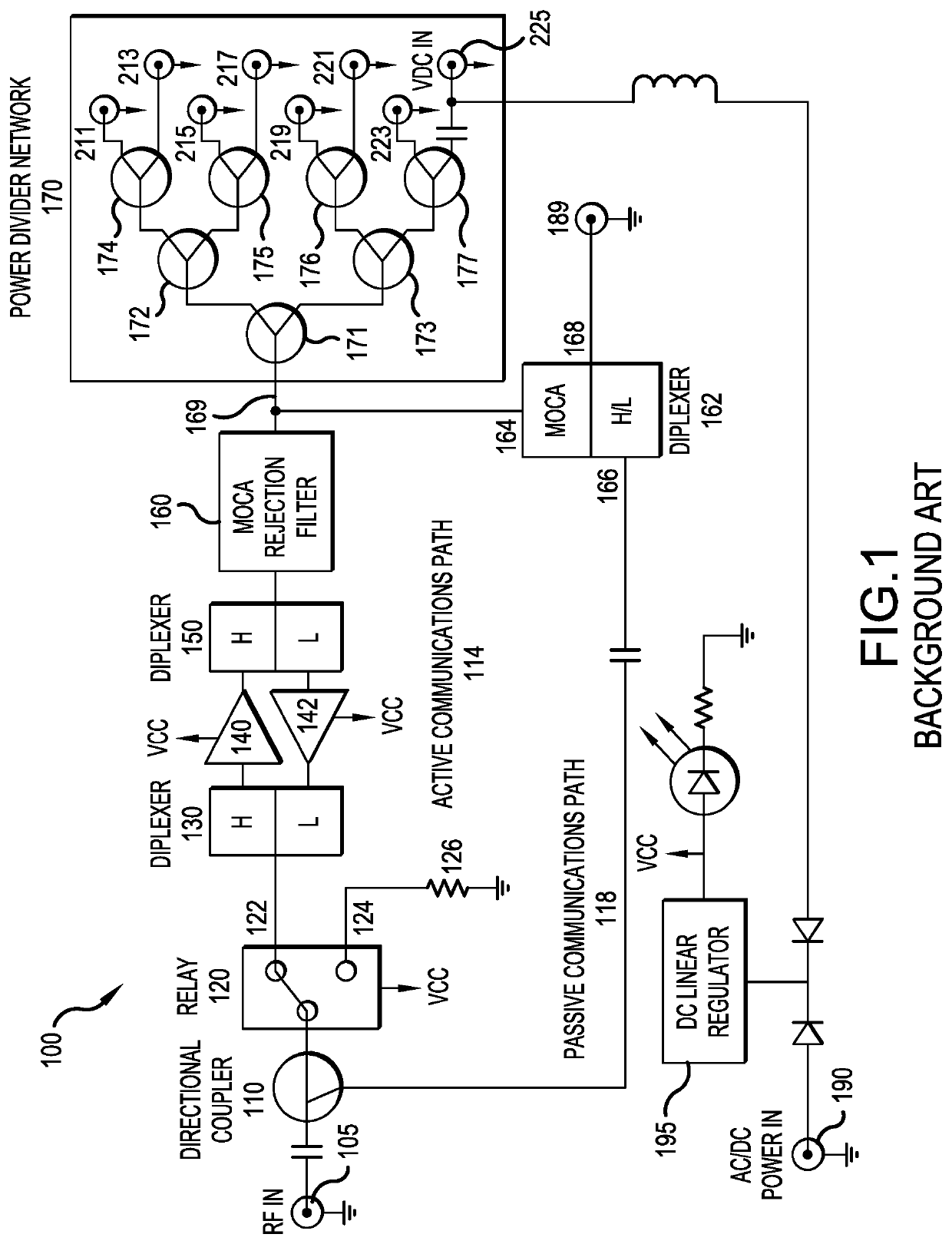
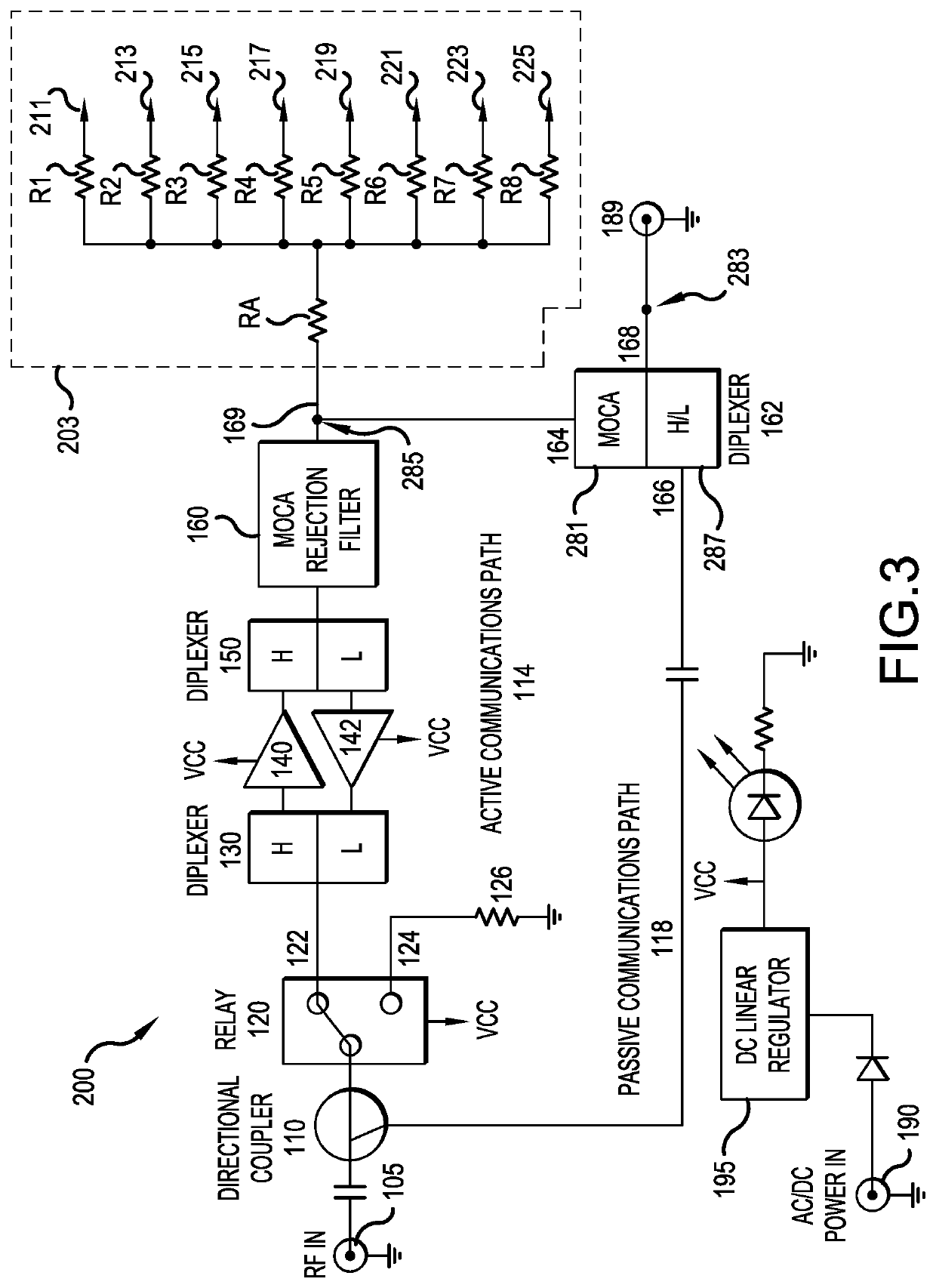
[0051]FIG. 3 is a block diagram of a CATV bi-directional RF signal amplifier 200, according to the present invention. The CATV RF amplifier 200 includes many of the same or similar elements, as compared to FIG. 1, and these elements have been labeled by the same reference numerals.

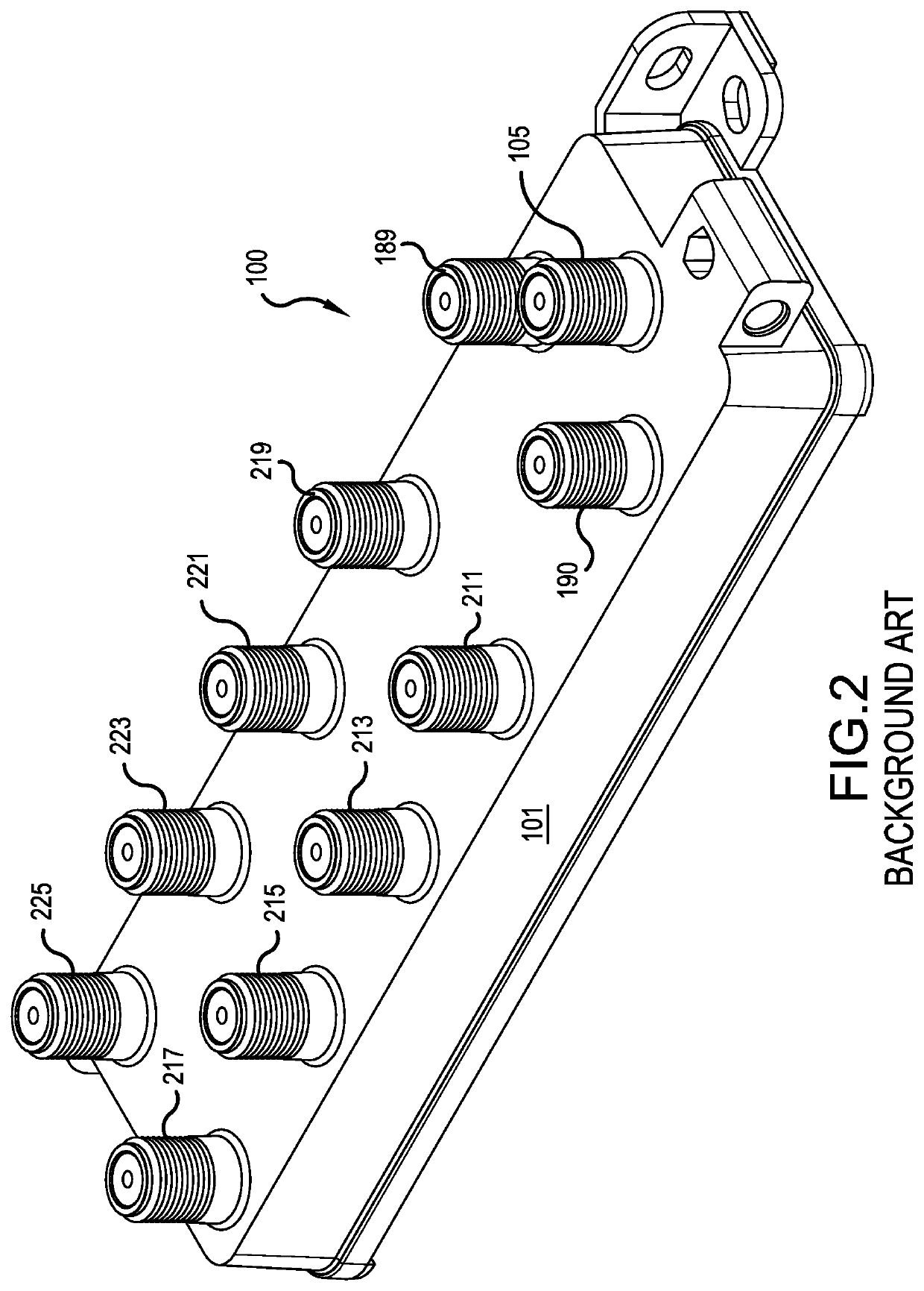
[0052]The CATV RF amplifier 200 is enclosed by a housing 101. In particular, the housing 101 may be the same as depicted in FIG. 2, although the dimension (length, width and thickness) may be slightly reduced due to the smaller components.

[0053]A RF input port 105 is located on the housing 101. The input port 105 receives downstream service provider signals and transmits upstream signals from customer devices to the service provider. As in the background art, the RF amplifier 200 includes a first or upstream diplexer 130 having a full frequency band terminal, a high frequency band terminal and a low frequency band terminal. The full frequency band terminal is connected to the input port 105, via a relay 12...

second embodiment

[0061]FIG. 4 is a block diagram of a CATV bi-directional RF signal amplifier 300, according to the present invention. The CATV RF amplifier 300 is identical to the CATV RF amplifier 200 of FIG. 3, except that the first and second diplexers 130 and 150 have been replaced by upstream and downstream directional couplers 301 and 303. The upstream and downstream directional couplers 301 and 303 in combination with the first and second amplifiers 140 and 142 form a full duplex amplifier, which will be briefly described below. More details concerning the full duplex amplifier can be found in the Assignee's co-pending application Ser. No. 62 / 740,550, which is herein incorporated by reference.

[0062]The full duplex amplifier has an upstream directional coupler 301. The upstream directional coupler 301 has a first terminal 11, a second terminal 13 and a third terminal 15. Signals passing between the first and third terminals 11 and 15 in either direction encounter a first level of attenuation....

third embodiment

[0068]In the embodiments of FIGS. 3 and 4, the resistive splitter network 203 includes only resistors. FIG. 5 is a block diagram of a CATV bi-directional RF signal amplifier 400, according to the present invention. The CATV RF amplifier 400 is identical to the CATV RF amplifier 200 of FIG. 3, except that the resistive splitter network 203 has been replaced with a modified resistive splitter network 403.

[0069]The modified resistive splitter network 403 includes a power divider 171 with a ferrite core to split an incoming signal received at an input leg 407 to two output legs 409 and 411. The power divider 171 also uses the ferrite core to combine signals received at the two output legs 409 and 411 to send the combined signal to the input leg 407.

[0070]A first plurality of resistors RA, R1, R2, R3 and R4 are connected to the first output leg 409 and are connected to first, second, third and fourth RF output ports 211, 213, 215 and 217. A second plurality of resistors RB, R5, R6, R7 an...


PUM


Abstract

The present invention is directed to a CATV & MoCA® device, such as a RF signal amplifier. The RF signal amplifier includes a RF input port to receive signals from, and transmit signals to, a service provider. The RF input port is connected to an active communication path with a downstream signal amplifier leading to an input of a resistive splitter network. The resistive splitter network has plural interconnected resistors, which split the amplified signal received at the input of the resistive splitter network and provide the signal to plural “CATV & MoCA®” output ports. Upstream CATV signals received by the “CATV & MoCA®” output ports are combined by the resistive splitter network and sent to the RF input port to be transmitted to the service provider. MoCA® signals received by any one of the “CATV & MoCA®” output ports are carried by the resistive splitter network to the other “CATV & MoCA®” output ports, and potentially to other “MoCA® only” ports of the RF signal amplifier.

Description

[0001]This application claims the benefit of U.S. Provisional Application Ser. No. 62 / 804,155, filed Feb. 11, 2019, which is herein incorporated by reference.BACKGROUND OF THE INVENTION1. Field of the Invention[0002]The present invention generally relates to radio frequency (“RF”) signal amplifiers and, more particularly, to signal amplifiers that support Multimedia Over Coax Alliance (“MoCA®”) communications. The present invention provides a RF signal amplifier within an active communication path leading to plural amplified output ports supported by a resistive splitter network.2. Description of the Related Art[0003]Cable television (“CATV”) networks are known types of communications networks that are used to transmit information between a service provider and a plurality of subscriber premises, typically over fiber optic and / or coaxial cables. The service provider may offer, among other things, cable television, broadband Internet and Voice-over-Internet Protocol (“VoIP”) digital ...

Claims


Application Information

Patent Timeline
Patent Type & Authority Patents(United States)
IPC IPC(8): H04N21/61H04L12/28H04N7/10H04N7/173
CPCH04N21/6118H04L12/2838H04N7/106H04N7/17309H04N21/6168H04N7/104H04L12/2801
Inventor LI, SHI MAN
Owner DIGICOMM INT LLC
Why Eureka
Try Eureka