
Assembly comprising a lubricating wheel and lubricant nozzles for a planetary gear speed reducer of a turbomachine

a technology of planetary gear speed reducer and turbomachine, which is applied in the direction of mechanical equipment, gearing details, machines/engines, etc., can solve the problems of difficult to reach the sun gear with oil, disadvantages of the type of reducer, and complex mounting, so as to achieve the effect of optimizing the lubrication of the reducer

Active Publication Date: 2021-09-07
SAFRAN TRANSMISSION SYST
View PDF9 Cites 1 Cited by
  • Summary
  • Abstract
  • Description
  • Claims
  • Application Information

AI Technical Summary

Benefits of technology

The patent describes a new nozzle design for lubricating gear assemblies. The nozzle has more material at the level of the oil projection orifices, which results in a boss-shaped design with larger oil orifices than previous nozzles. This allows the oil to be guided over a longer distance and projected closer to the gear assemblies, improving lubrication. The nozzle also has tabs that are recessed or countersunk to ensure proper alignment between the nozzle and the gear assemblies. The new design ensures a captive nozzle and secure assembly.

Problems solved by technology

However, this type of reducer has disadvantages.
One of the problems is linked to the correct lubrication of the gearings of the planetary carriers and of the sun gear.
At high speed, it is difficult to reach the sun gear with the oil, due to the centrifugal effect.
Another of the problems is linked to the complexity of the mounting.

Method used


Image

  • Assembly comprising a lubricating wheel and lubricant nozzles for a planetary gear speed reducer of a turbomachine
  • Assembly comprising a lubricating wheel and lubricant nozzles for a planetary gear speed reducer of a turbomachine
  • Assembly comprising a lubricating wheel and lubricant nozzles for a planetary gear speed reducer of a turbomachine

Examples


Embodiment Construction

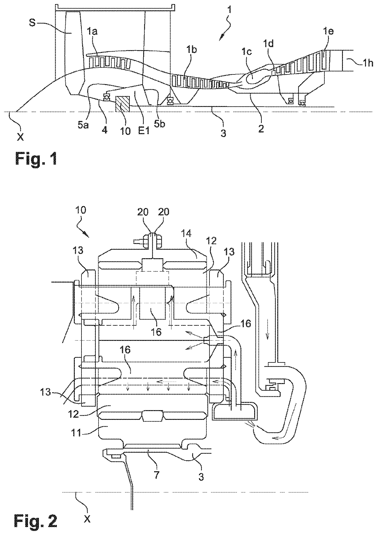
[0053]FIG. 1 shows a turbine engine 1 which comprises, conventionally, a fan blade S, a low-pressure compressor 1a, a high-pressure compressor 1b, an annular combustion chamber 1c, a high-pressure turbine 1d, a low-pressure turbine 1e and an exhaust pipe 1h. The high-pressure compressor 1b and the high-pressure turbine 1d are connected by a high-pressure shaft 2 and form with it, a high-pressure (HP) body. The low-pressure compressor 1a and the low-pressure turbine 1e are connected by a low-pressure shaft 3 and form with it, a low-pressure (LP) body.

[0054]The fan blade S is driven by a fan shaft 4 which is coupled to the LP shaft 3 by means of a planetary gear reducer 10 represented here schematically.

[0055]The reducer 10 is positioned in the front portion of the turbine engine. An attached structure schematically comprising, here, an upstream portion 5a and a downstream portion 5b is arranged so as to form an enclosure E1 surrounding the reducer 10. This enclosure E1 is here closed...


PUM


Abstract

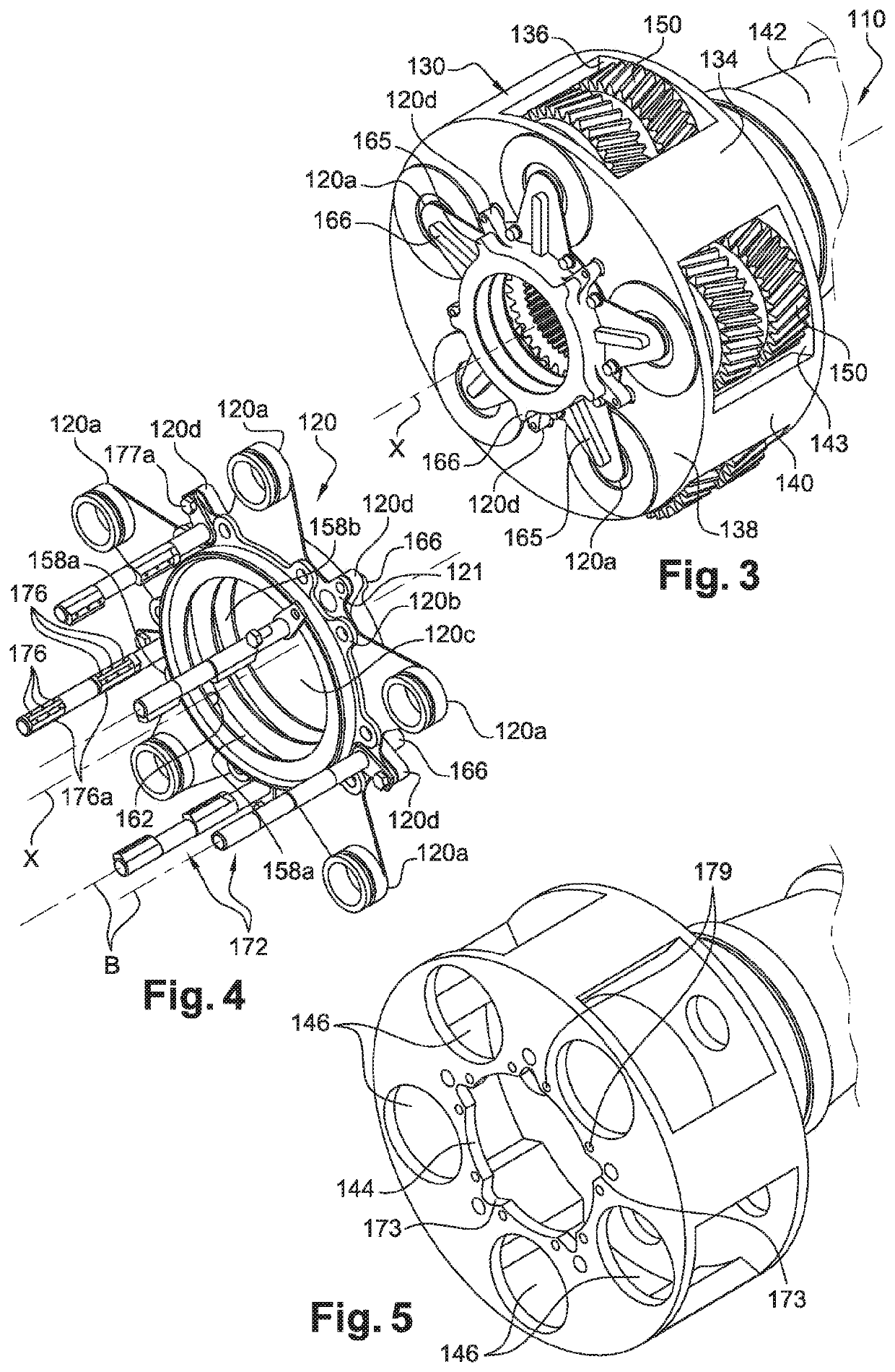
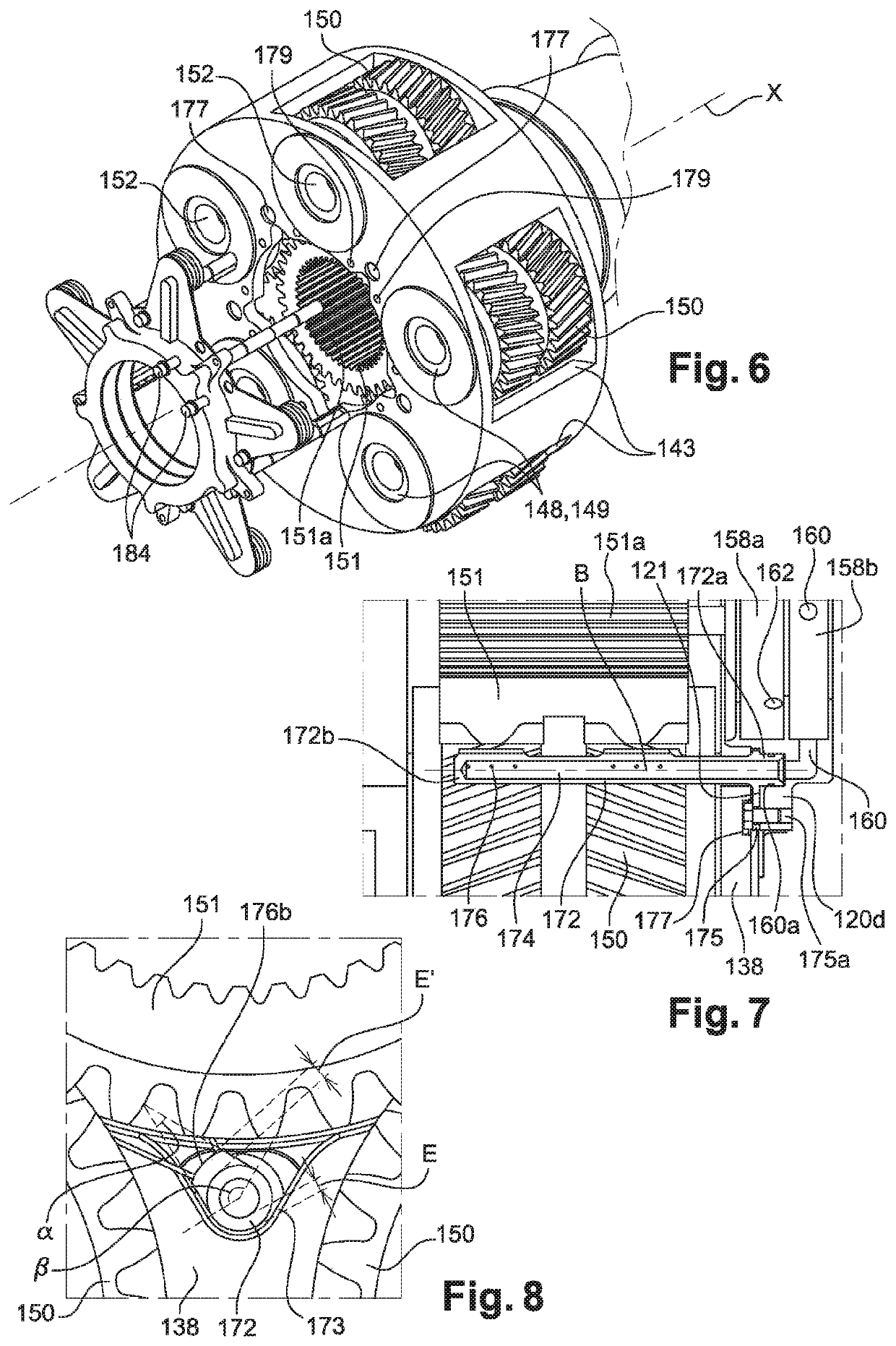
An assembly comprising a lubricating wheel and lubricant nozzles for a planetary gear speed reducer of a turbomachine, the wheel having a lubricator configured to supply lubricant to the nozzles and the bearings of the planetary carriers of the reducer, the wheel being intended to be mounted coaxially on an annular wall of an axis of rotation X of a planetary carrier of the reducer, the wheel having a bearing and attachment surface on the annular wall of the planetary carrier, the lubricant nozzles being distributed around the axis and each having a generally elongated shape, the nozzles having first longitudinal ends for fluidly connecting to the lubricator of the wheel, wherein the first ends of the nozzles being configured to be attached to the wheel before mounting the wheel on the annular wall of the planetary carrier.

Description

FIELD OF THE INVENTION[0001]The present invention relates to the field of planetary gear speed reducers for turbine engines, in particular aircraft turbine engines, as well as elements which form a reducer of this type such as nozzles, a planetary carrier, a wheel, etc.STATE OF THE ART[0002]The state of the art comprises, in particular, the documents WO-A1-2010 / 092263, FR-A1-2 987 416, FR-A1-3 036 763, WO-A2-2014 / 099087, US-A1-2012 / 028756 and FR-A1-3 041 054.[0003]Current turbine engines, in particular turbine engines comprising one or more propellers blowing a secondary flow, comprise a transmission system, termed reducer, to drive this or these blades at the correct rotation speed from the shaft of the power turbine of the primary body of the engine.[0004]The functioning of the reducers, in particular on turbine engines with a fan blade with a high dilution rate, requires a particularly high oil flow, of around 6,000 to 7,000 litres per hour on take-off, to ensure the lubrication ...

Claims


Application Information

Patent Timeline
Patent Type & Authority Patents(United States)
IPC IPC(8): F16H57/04F16H57/08F01D25/18F02C7/36
CPCF16H57/0482F01D25/18F02C7/36F16H57/0431F16H57/0456F16H57/0479F16H57/082F05D2220/323F05D2250/11F05D2250/12F05D2250/13F05D2260/40311F05D2260/98F16H57/0409F16H57/0457F16H57/0486F16H57/023
Inventor DOMBEK, ALEXIS CLAUDE MICHELDI GIOVANNI, JEAN-CHARLES MICHEL PIERRE
Owner SAFRAN TRANSMISSION SYST
Learn More