Wind turbine steel tower ring segment and method

a technology of wind turbines and steel towers, applied in the direction of towers, buildings, constructions, etc., can solve the problems of increasing the cost of manufacturing a wind turbine. , to achieve the effect of reducing the cost of a wind turbine, and increasing the working safety

Active Publication Date: 2021-09-14
WOBBEN PROPERTIES GMBH
View PDF15 Cites 2 Cited by
  • Summary
  • Abstract
  • Description
  • Claims
  • Application Information

AI Technical Summary

Benefits of technology

[0009]Provided is a wind turbine steel tower ring segment, a wind turbine tower portion, a wind turbine tower, a wind turbine and a method for producing a wind turbine tower portion and may alleviate or eliminate one or more of the stated disadvantages. Provided are techniques which reduces the costs of a wind turbine, in particular the costs of manufacturing and / or assembling a wind turbine tower, and / or increases working safety during the manufacture and / or assembly of a wind turbine.
[0020]The connection element has the particular advantage that functional elements can be arranged here at low cost. These may for example be supporting structures on which assembly pedestals are arranged. Furthermore, supply devices such as cables or cable harnesses or cable harness holding devices may also be arranged on the connection elements.
[0021]In a preferred design variant of the wind turbine steel tower ring segment, provision is made whereby the first vertical flange and / or the second vertical flange and the connection element enclose the same angle with the shell segment, and / or the connection element encloses a connection angle with the shell segment, which connection angle differs from a flange angle which the first vertical flange and / or the second vertical flange enclose(s) with the shell segment. In this design variant, the first vertical flange and / or the second vertical flange can thus be arranged in alignment with the connection element. The connection element preferably forms, so to speak, an elongation of the first vertical flange and / or the second vertical flange. The connection element can thus be arranged particularly inexpensively on the first vertical flange and / or the second vertical flange, wherein simplifications in the course of the manufacturing process are also made possible. Alternatively, the connection elements project in a different direction than the vertical flanges.
[0026]In particular, it is preferable for the connection thickness and the flange thickness to have the same dimension. It is furthermore preferable for the wind turbine steel tower ring segment to comprise a first connection element and a second connection element, wherein the shell segment extends in the direction of the segment height from an upper end to a lower end and / or the first connection element is arranged on the first vertical flange and the second connection element is arranged on the second vertical flange, and wherein the first connection element and the second connection element have the same spacing to the upper end and / or the lower end. This design variant has the advantage in particular that a functional element, in particular a supporting structure, can be arranged on the first connection element and on the second connection element, and a substantially horizontally oriented connecting path between the two connection elements is made possible.
[0031]A recess in the bending portion has the particular advantage that the bending process is optimized, in particular by virtue of the required bending forces being reduced. Furthermore, single-piece wind turbine steel tower ring segments with particularly large wall thicknesses are made possible for the first time by such a recess, because the bending forces in the case of large wall thicknesses are too high. The recess may be produced for example by milling and / or gouging. In particular, it is preferable for the recess to be introduced into a flat starting material and, in a subsequent processing process, for the starting material to be bent in such a way that a shell segment and a vertical flange are formed, wherein the recess is located in the bending portion.
[0038]The wind turbine tower with at least one above-described wind turbine steel tower ring segment and with at least one bracket steel tower portion makes it possible to combine the advantages of the two configurations with one another. In particular in the regions in which the wind turbine tower is subjected to particularly high loads, which is generally the case in the lower region, it is preferable to use a bracket steel tower portion. In particular in the regions in which the wind turbine tower is subjected to relatively low loads, which is generally the case in the upper region, it is preferable to use an above-described steel tower ring segment.

Problems solved by technology

Towers of wind turbines, in particular of modern horizontal-axis wind turbines, account for a major part of the total costs of manufacturing a wind turbine.
In particular, the increasing rotor diameters and power outputs of wind turbines mean that the towers are also becoming larger and / or are being subjected to higher loads.
In particular, the manufacture and / or assembly and / or the logistics of the towers is or are time-consuming and expensive.
In particular in the case of segmented steel towers, in particular in the case of steel towers which are segmented in a circumferential direction, distortion is often found, which complicates the assembly of the tower.

Method used


Image

  • Wind turbine steel tower ring segment and method
  • Wind turbine steel tower ring segment and method
  • Wind turbine steel tower ring segment and method

Examples


Embodiment Construction

[0060]In the figures, identical or substantially functionally identical or similar elements are denoted by the same reference designations.

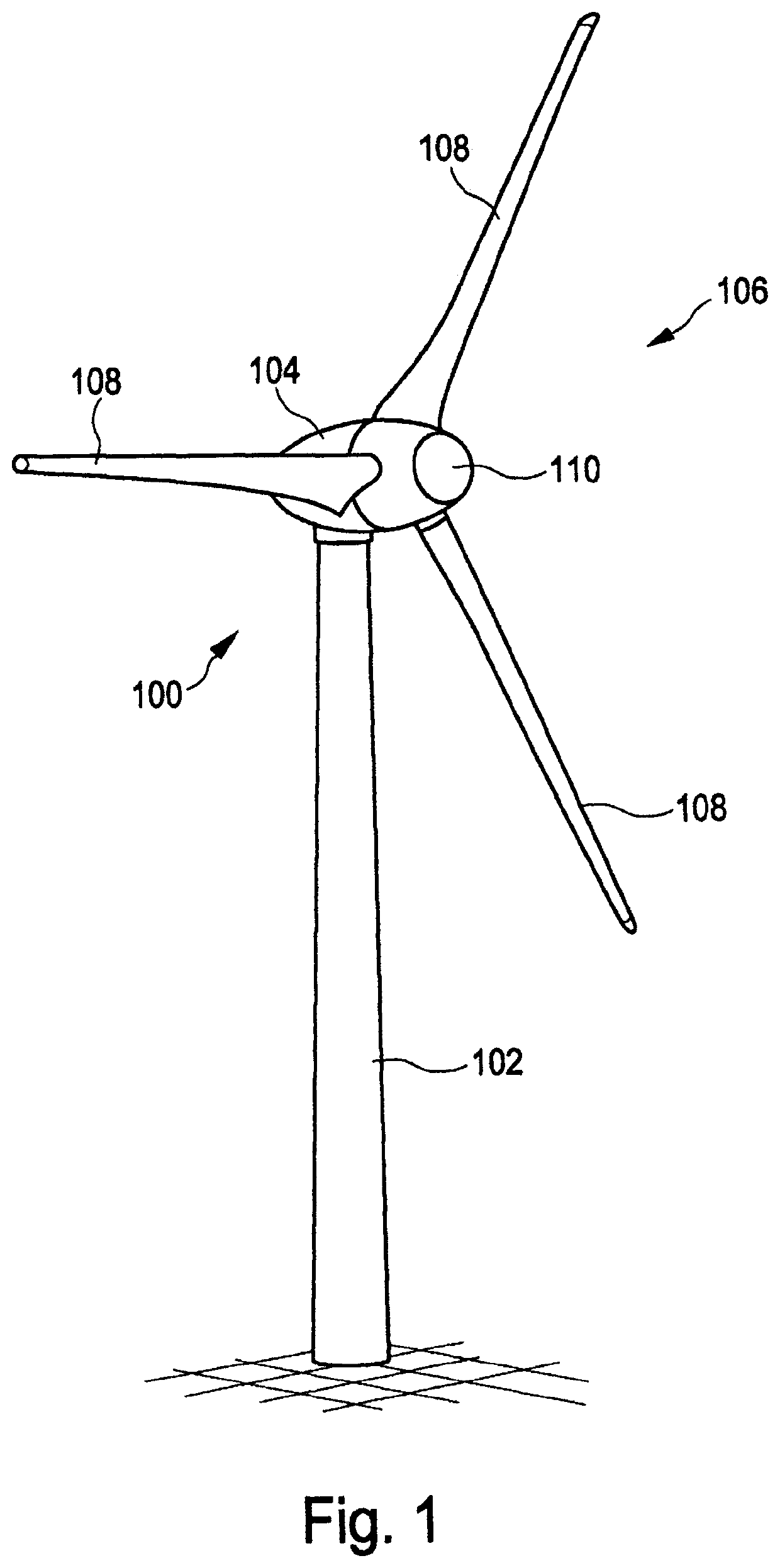
[0061]FIG. 1 shows a schematic three-dimensional view of an exemplary embodiment of a wind turbine. FIG. 1 shows in particular a wind turbine 100 with a tower 102 and a nacelle 104. A rotor 106 having three rotor blades 108 and having a spinner 110 is arranged on the nacelle 104. During operation, the rotor 106 is set in rotational motion by the wind and in this way drives a generator at the nacelle 104. The tower 102 comprises in particular a plurality of wind turbine steel tower ring segments with connection elements which are arranged at vertical flanges and which serve for the arrangement of functional elements.

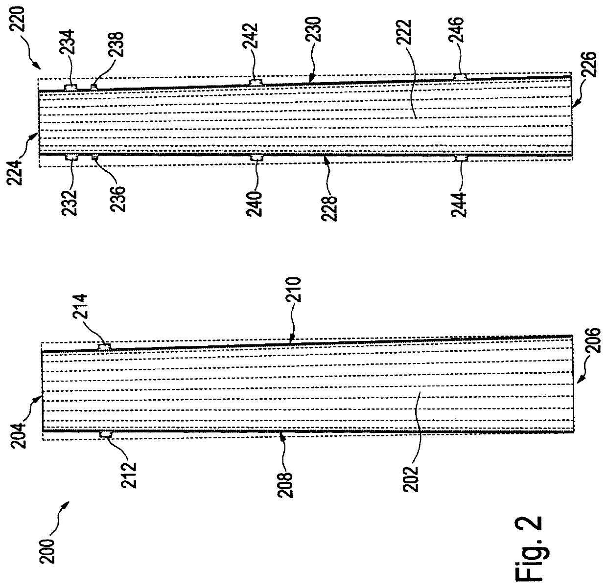
[0062]FIG. 2 shows a schematic two-dimensional view of two exemplary embodiments of wind turbine steel tower ring segments. The shell segment 202 of the steel tower ring segment 200 extends from an upper horizontal joint side 204 to a ...


PUM


Abstract

A wind turbine steel tower ring segment, a wind turbine tower portion, a wind turbine tower, a wind turbine and a method for producing a wind turbine tower portion. A wind turbine steel tower ring segment for a wind turbine tower, comprising a shell segment with an extent in the direction of a segment height, of a segment ring direction and of a segment thickness and with a first horizontal joint side and a second horizontal joint side, a first vertical joint side and a second vertical joint side, wherein a first vertical flange is arranged at the first vertical joint side and / or a second vertical flange is arranged at the second vertical joint side, wherein the first vertical flange and / or the second vertical flange enclose(s) an angle with the shell segment, wherein at least one connection element for the arrangement of functional elements is formed on the first vertical flange and / or on the second vertical flange, wherein the connection element projects from the first vertical flange and / or the second vertical flange.

Description

BACKGROUNDTechnical Field[0001]The invention relates to a wind turbine steel tower ring segment, a wind turbine tower portion, a wind turbine tower, a wind turbine and a method for producing a wind turbine tower portion.Description of the Related Art[0002]Wind turbines are known. Modern wind turbines generally concern so-called horizontal-axis wind turbines, in the case of which the rotor axis is arranged substantially horizontally and the rotor blades sweep through a substantially vertical rotor area. Aside from a rotor arranged at a nacelle, wind turbines generally comprise a tower on which the nacelle with the rotor is arranged so as to be rotatable about a substantially vertically oriented axis.[0003]Towers are generally slim structures which preferably have a large height and which furthermore preferably have relatively small dimensions orthogonally with respect to this height. Towers are preferably composed substantially of concrete and / or steel or comprise these materials. Th...

Claims


Application Information

Patent Timeline
Patent Type & Authority Patents(United States)
IPC IPC(8): E04H12/08F03D13/20E04H12/34
CPCE04H12/085E04H12/34F03D13/20F05B2230/60F05B2240/912F05B2240/40F03D13/10
Inventor KERSTEN, ROY
Owner WOBBEN PROPERTIES GMBH
Why Eureka
Try Eureka