Display panel

a display panel and display technology, applied in the field of display panels, can solve the problems of affecting the original function of the electronic device, and achieve the effect of reducing the effect of the loop antenna on the display function of the display panel, high light transmittance, and high light transmittan

Active Publication Date: 2021-09-21
AU OPTRONICS CORP
View PDF13 Cites 1 Cited by
  • Summary
  • Abstract
  • Description
  • Claims
  • Application Information

AI Technical Summary

Benefits of technology

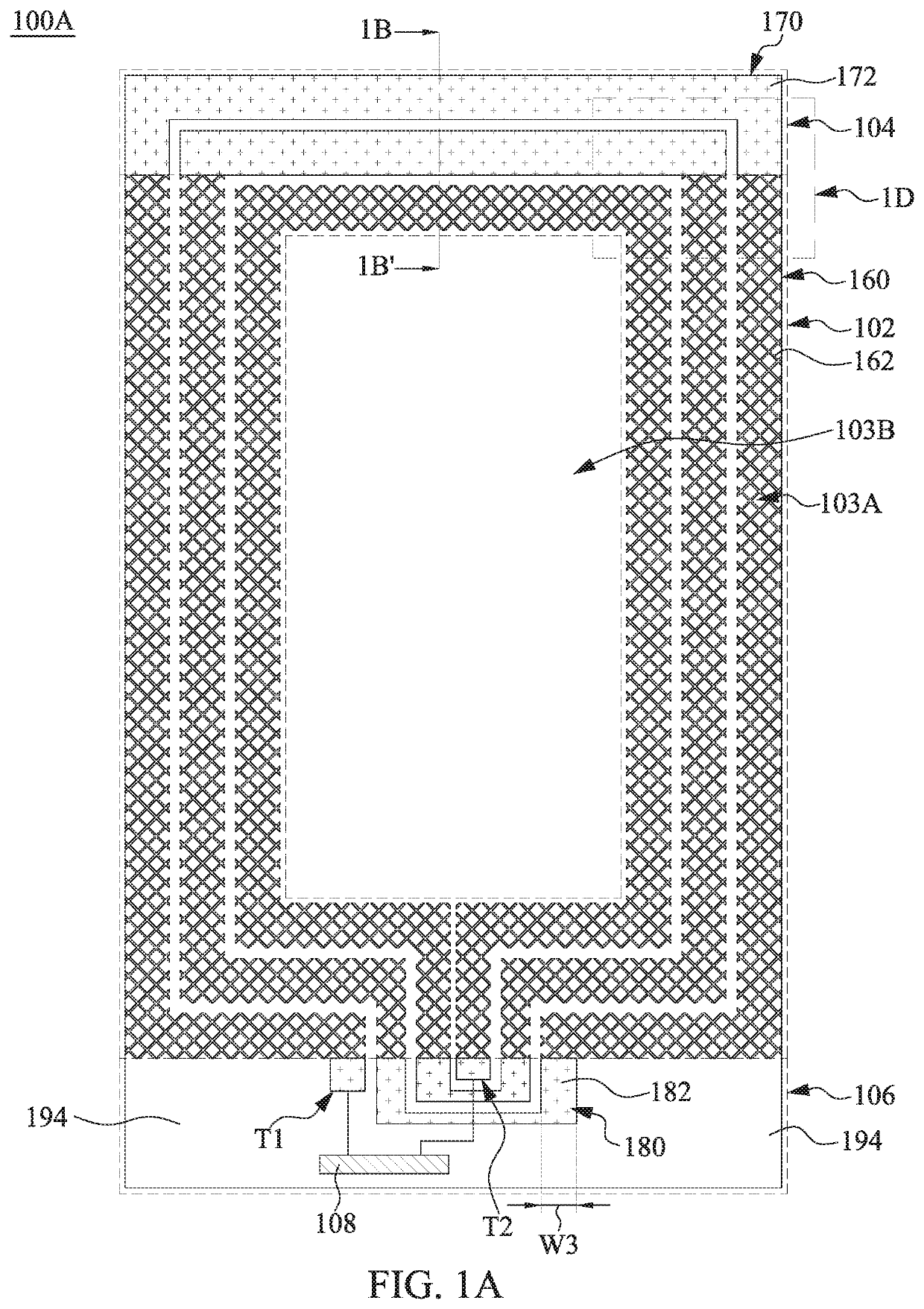
[0014]With the aforementioned configuration, the first loop pattern, the second loop pattern, and the bridging pattern may collectively form the loop antenna. Since the mesh structure of the first loop pattern can have high light transmittance, the loop antenna also has high light transmittance in the portion corresponding to the display area. Therefore, the effect of the loop antenna on the display function of the display panel can be reduced. By the difference in size of the wirings, the second loop pattern and the bridging pattern can reduce the impedance of the loop antenna, thereby increasing the strength of the magnetic field and enhancing the transmission energy of the wireless communication. In addition, since the number of the lower impedance area of the loop antenna is more than one, it can help balance the magnetic field distribution generated by the loop antenna by coupling.

Problems solved by technology

In this regard, since the addition of the near-field wireless communication function to the portable electronic device increases the complexity of the structure, the original function of the electronic device is affected.

Method used


Image

  • Display panel
  • Display panel
  • Display panel

Examples


Embodiment Construction

[0023]In the following detailed description, for purposes of explanation, numerous specific details are set forth in order to provide a thorough understanding of the disclosed embodiments. It will be apparent, however, that one or more embodiments may be practiced without these specific details. In other words, in some embodiments of the present invention, these practical details are not necessary. Moreover, some well-known structures and devices are schematically depicted in order to simplify the drawings.

[0024]In the present invention, it is comprehensible that terms such as first, second, and third are used to describe various elements, components, areas, layers and / or blocks. The terms are used for identifying single element, component, area, layer and / or block. Therefore, the following first element, component, area, layer and / or block may also be called as the second element, component, area, layer and / or block without departing from the intention of the present invention. “Ap...


PUM

PropertyMeasurementUnit
widthaaaaaaaaaa
widthaaaaaaaaaa
widthaaaaaaaaaa

Abstract

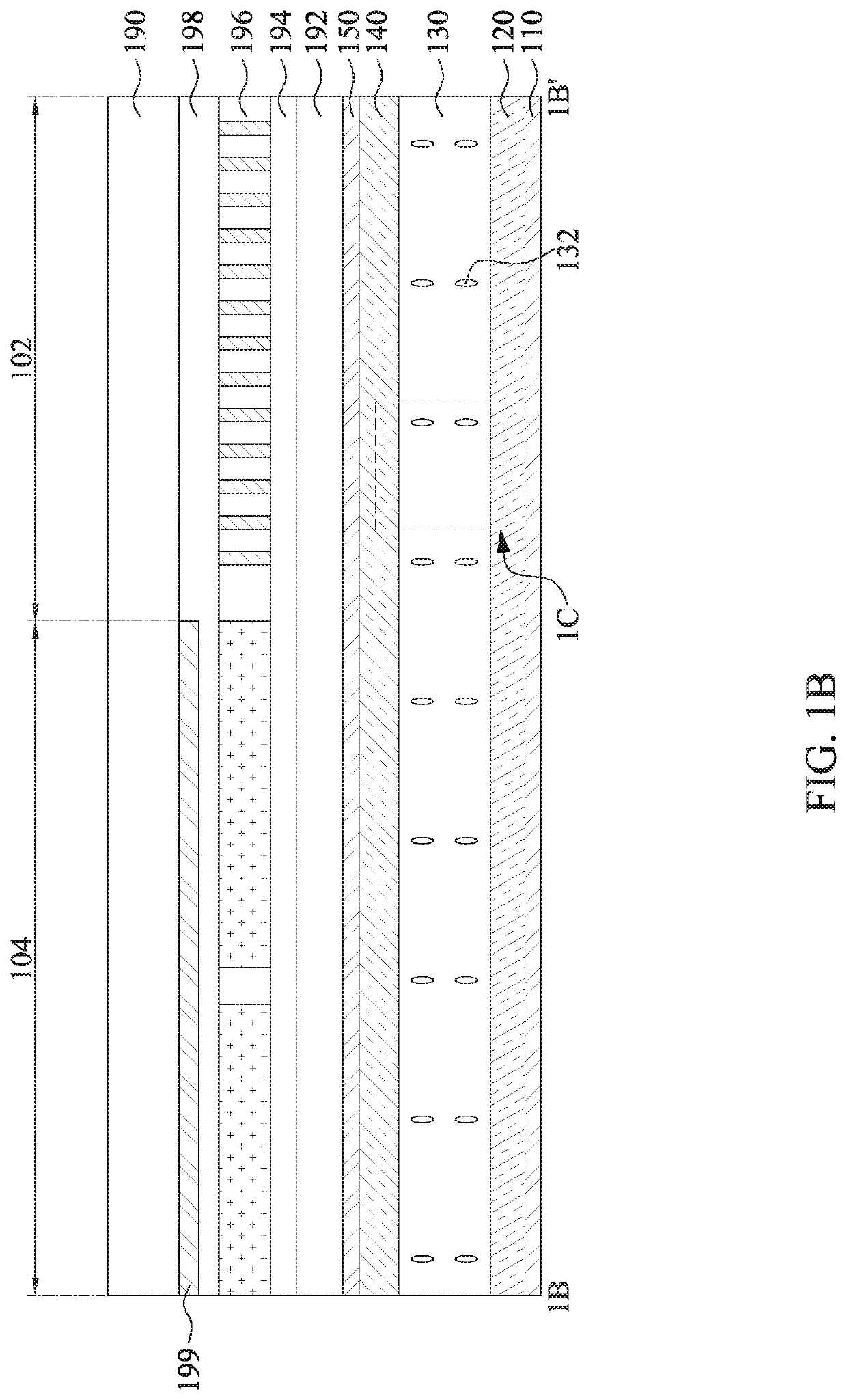
A display panel has a display area, a first wiring area, and a second wiring area, in which the display area is adjacent to the first and second wiring areas. The display panel includes a plurality of pixels, a first loop pattern, and a second loop pattern. The pixels are arranged within the display area. The first loop pattern is arranged within the display area and is located above the pixels. The first loop pattern includes a first wiring. The second loop pattern is arranged within the first wiring area and is located outside the second wiring area. The second loop pattern is electrically connected to the first loop pattern and includes a second wiring, in which the wiring width of the first wiring is smaller than the wiring width of the second wiring.

Description

[0001]This application claims priority to Taiwan Application Serial Number 108106878, Feb. 27, 2019, which is herein incorporated by reference in its entirety.BACKGROUNDTechnical Field[0002]The present disclosure relates to a display panel.Description of Related Art[0003]With the development of technology, various portable electronic devices have gradually become mainstream products in the consumer market, such as smart phones, smart watches, tablets or notebooks. The functions of these portable electronic devices are also becoming more and more abundant with market trends. For example, the function of near-field wireless communication may be added to the smart phone, such that the smart phone is able to perform the payment function via the near-field wireless communication function. In this regard, since the addition of the near-field wireless communication function to the portable electronic device increases the complexity of the structure, the original function of the electronic ...

Claims


Application Information

Patent Timeline
Patent Type & Authority Patents(United States)
IPC IPC(8): G06F1/16G02F1/1362
CPCG06F1/1698G02F1/136286G02F1/1333G02F1/133H01Q1/22G02F1/1313G06F1/1637H04B5/0081
Inventor CHEN, YA-TINGCHENG, SHENG-WEN
Owner AU OPTRONICS CORP
Why Eureka
Try Eureka